HyperWorks Solvers

Elements

Elements

Previous topic Next topic Expand/collapse all hidden text  

Elements

Previous topic Next topic JavaScript is required for expanding text JavaScript is required for the print function  
hmtoggle_plus1The run stopped with the message: "Zero or Negative Volume", when solid elements are used with Ismstr=2 and /DT/BRICK/CST; is this normal?

Ismstr =1, 2 and 3 are not available for the 8 integration points solids using formulations Isolid =12 and 112.

This means that these solids continue to use large strain formulation, and the following error message appears:

"Zero or Negative Volume"

In order to use this small strain formulation with 8 integration points solid elements, use the HA8 solid formulation.

When using this formulation, set Isolid =14 with Inpts =222 (corresponding to Isolid =222 in input format 44). Also set Icpre =1 for elastic or visco-elastic material law, and Icpre =2 for elasto-plastic laws.

hmtoggle_plus1I used solid elements and several integration points, and Starter the following error message appears, while the element seems to be well-defined: ** ERROR:  ZERO OR NEGATIVE 3D SOLID VOLUME, is this normal?

** ERROR:  ZERO OR NEGATIVE 3D SOLID VOLUME

ZERO OR NEGATIVE VOLUME 3D-ELEMENT NB 1


faq_elements3

In the figure above, the volume of the element is positive, but the sub-volume associated to one integration point is negative.

The solid is decomposed into sub-volumes associated to each integration point. If the element is badly warped, one sub-volume could be negative.

hmtoggle_plus1How many integration points should be used in the thickness of shell elements?

If only one integration point is used, a membrane only behavior will be obtained (except with law 1). Some materials, such as fabric, can justify such a choice (no bending strength).

In case of an elastic behavior, one gets the exact solution from three integration points – that is to say that the bending moments are exactly integrated through the thickness of the shell – and it is not necessary to use more integration points.

In case of a plastic behavior, the bending moments are not integrated exactly. Using more integration points, the solution becomes more accurate; so it is recommended to use five integration points.

faq_elements4

hmtoggle_plus1With shell elements using the same material law, but different types of properties (while keeping the same number of integration points), I do not get the same results; why?

The integration scheme which is used for property types 1 and 9 (relative to isotropic shells through the thickness) sets the integration points and weights in order to integrate exactly the bending moments in the elastic case (from three integration points since for one integration point, no bending moments are computed).

The integration scheme which is used for property types 10 and 11 is a step-by-step integration scheme and uses integration points at the center of each layer, and weights which correspond to the relative thickness of each layer. So the integration scheme is not the same one.

An error relatively important can occur in the elastic field, when there are a few layers or large differences on the thicknesses of the layers. One way to work around this problem is to subdivide the thicker layers. But it is generally not well-suited for modeling the failure of the layers.

faq_elements6

Elastic case:

Stress is linear through the thickness; an integration of forces step-by-step is exact.

But the integration of moments, step-by-step is not exact since symbol(z) z is quadratic.

hmtoggle_plus1When is it better to use QEPH shells instead of Belytschko shells?

QEPH shells are more accurate for elastic or elasto-plastic loads, whatever the loading type - quasi-static or dynamic; but they are not recommended with anisotropic and orthotropic material laws.

QEPH shells will give better results if the mesh is fine enough. For a coarse mesh, this formulation will be too stiff and some local buckling phenomena could be missed - the Belytschko shells provide better results.

QEPH/HEPH is not recommended for orthotropic materials because the stabilization forces are computed based on isotropic assumptions.

hmtoggle_plus1I used solid elements and the run stopped before the end time, with the message: "Zero or Negative Volume": How can this problem be solved?

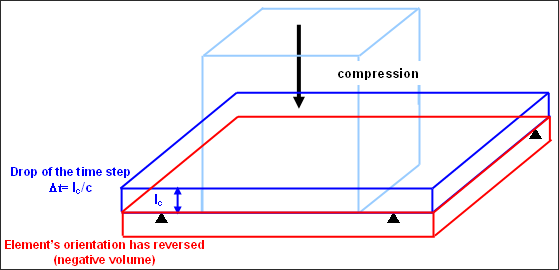
This happens when solid elements are very deformed and their characteristic length goes to 0. You may notice the time step of the element written into the message drops down in the output file before this error message appears.

For large strain formulation, the time step of an element goes to 0 when the element is compressed. In a mathematical way, the element can not reverse its orientation since its stiffness increases to an infinite value; but due to numerical accuracy, the element may go to reverse its orientation.

faq_elements1

In order to solve the problem of both the drop in cycle time step and subsequent termination of the run due to a negative volume, you might first check that the material used is well-suited to the physics which is represented. Then switch the elements to small strain formulation. This is done as follows:

In RADIOSS Starter input file (Runname_0000.rad), use Ismstr =2 in the solid property or in the option /DEF_SOLID; in RADIOSS Engine file (Runname_0001.rad) use the option /DT/BRICK/CST which will set the time step value symbol_tritmin at which the solid elements will switch to small strain.

This means that the solid elements using Ismstr =2 will use large strain formulation while their time step remains greater than symbol_tritmin, and will then switch to small strain formulation.

Their volume will then remain constant and the element can even reverse its orientation. The drop of their time step normally stops except for some materials, especially viscous materials.