OptiStruct uses the S-N approach for calculating the fatigue life. The S-N approach is suitable for high cycle fatigue, where the material is subject to cyclical stresses that are predominantly within the elastic range. Structures under such stress ranges should typically survive more than 1000 cycles.
The S-N approach is based on elastic cyclic loading, inferring that the S-N curve should be confined to numbers greater than 1000 cycles. This ensures that no significant plasticity is occurring. This is commonly referred to as high-cycle fatigue.
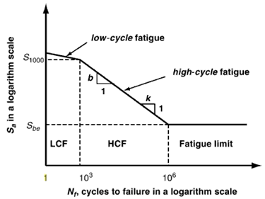
Figure 1: Low Cycle and High Cycle regions on the S-N curve
Since S-N theory deals with uniaxial stress, the stress components need to be resolved into one combined value for each calculation point, at each time step, and then used as equivalent nominal stress applied on the S-N curve (Figure 2).
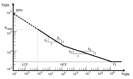
Figure 2: Two segment S-N curve
In OptiStruct various stress combination types are available, with the default being “Absolute maximum principle stress”. In general “Absolute maximum principle stress” is recommended for brittle materials, while “Signed von Mises stress” is recommended for ductile material. The sign on the signed parameters is taken from the sign of the Maximum Absolute Principal value.
In this tutorial, you will be able to evaluate fatigue life with the S-N method through process manager step by step. In brief, the following contents are covered:
| • | Launching Fatigue Process Manager |
| • | Creating fatigue subcase |
| • | Defining fatigue analysis parameters |
| • | Defining fatigue elements and S-N properties |
| • | Defining load-time history and loading sequence |
| • | Viewing results summary and launch HyperView for post-processing |
The following files found in the optistruct.zip file are needed to perform this tutorial. Refer to Accessing the Model Files.
ctrlarm.fem, load1.csv and load2.csv
|
|
Exercise
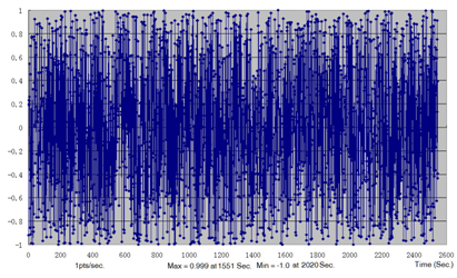
A control arm loaded by brake force and vertical force is used, as shown in Figure 3. Two load time histories acquired for 2545 seconds with 1 HZ, shown in Figures 4(a) and 4(b), are applied. The material of the control arm is aluminum, whose S-N curve is shown in Figure 5. Because a crack always initiates from the surface, a skin meshed with shell elements is designed to cover the solid elements, which can improve the accuracy of calculation as well.
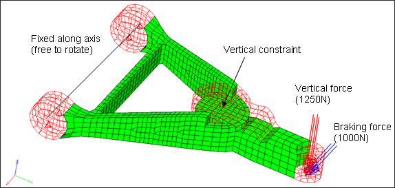
Figure 3: Model of control arm for fatigue analysis
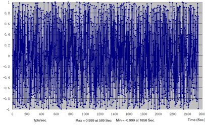
(a)
(b)
Figure 4: Load time history (a) for vertical force (b) for braking force
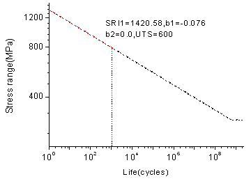
Figure 5: S-N Curve of Aluminum
Step 1: Launch HyperMesh and Process Manager
| 1. | Launch HyperMesh 2017. A User Profiles Graphic User Interface (GUI) will appear. |
| 2. | Select OptiStruct in the User Profiles dialog. |
| 4. | Click Tools > Fatigue Process > Create New. |
| 5. | Input New Session Name and Working Folder and click Create. This creates a new file to save the instance of the currently loaded fatigue process template. |
When finished, the Fatigue Analysis tree will appear.
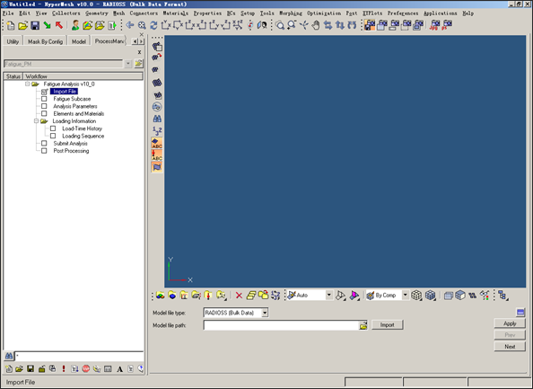
Figure 6: Glance after launch Fatigue Process Manager (FPM)
Step 2: Import model
| 1. | Make sure the task Import File is selected in the Fatigue Analysis tree. |
| 2. | For the Model file type:, select OptiStruct. |
| 3. | Click the Open model file icon  . A Select File browser window opens. . A Select File browser window opens. |
| 4. | Select the ctrlarm.fem file you saved to your working directory from the optistruct.zip file and click Open. Refer to Accessing the Model Files. |
This loads the control arm model. It includes a whole definition of two static subcases, elements sets, and material static properties, etc.
| 6. | Click Apply. This guides you to the next task Fatigue Subcase of the Fatigue Analysis tree. |
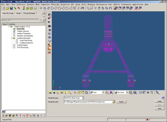
Figure 7: Import a Finite Element Model file
Step 3: Create fatigue subcase
| 1. | Make sure the task Fatigue Subcase is selected in the Fatigue Analysis tree. |
| 2. | In the Create new fatigue subcase field, enter fatsub_fpmtut. |
| 4. | For the Select existing fatigue subcase:, select the newly created fatigue subcase fatsub_fpmtut. |
fatsub_fpmtut is selected as the active fatigue subcase. Definitions in the following processes (analysis parameters, fatigue elements and properties, loading sequences, etc.) will be for this subcase.
This saves the current definitions and guides you to the next task Analysis Parameters of the Fatigue Analysis tree.
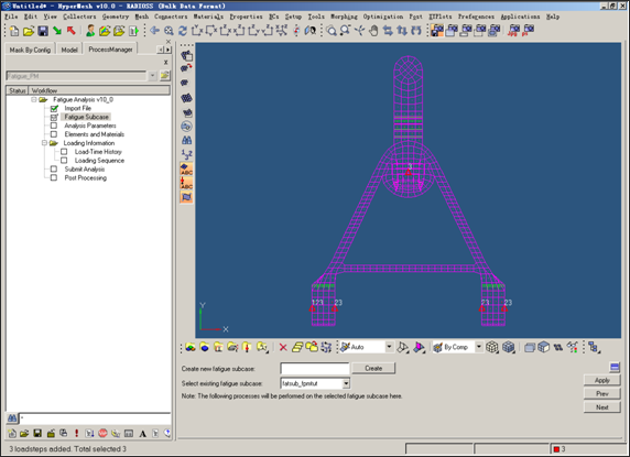
Figure 8: Create and select active fatigue subcase to process
Step 4: Fatigue Analysis Parameters Definition
| 1. | Make sure the task Analysis Parameters is selected in the Fatigue Analysis tree. |
| 2. | Select the following options: |
Analysis type
|
S-N
|
Stress combination method
|
Signed von Mises
|
Mean stress correction
|
GERBER
|
FEA stress unit
|
MPA
|
Rainflow type
|
STRESS
|
| 3. | Enter the following values: |
Gate
|
0.0
|
Certainty of survival
|
0.5
|
This saves the current definitions and guides you to the next task Elements and Materials of the Fatigue Analysis tree. For details, consult the HyperWorks 2017 help.
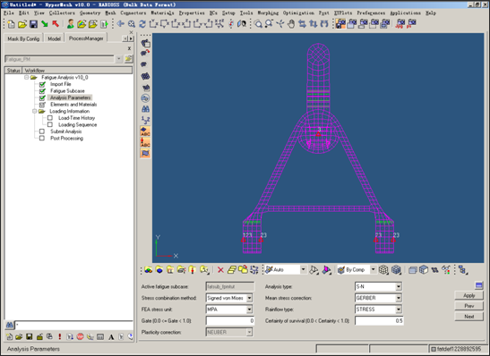
Figure 9: Fatigue analysis parameters definition.
Step 5: Fatigue Elements and Materials Definition
| 1. | Make sure the task Elements and Materials is selected in the Fatigue Analysis tree. |
| 2. | Click Add. A Material Data window opens. |
| 3. | For Element entity type, select Property - PSHELL. |
| 4. | For Element entity name, select shell. This is the skin coating the solid control arm. |
| 5. | Make sure Ultimate tensile strength (UTS) is selected to define the material data. |
| 6. | For UTS, enter the value 600. |
| 7. | For Input method of defining S-N curve, select Estimate From UTS. |
| 8. | Click the Show SN curve definition icon  . An SN method description window introducing how to generate the SN material parameter opens. . An SN method description window introducing how to generate the SN material parameter opens. |
| 10. | For Material type, select Aluminum Alloys and click Estimate. All the data for SN curve definition are automatically estimated. |
| 11. | Click Plot SN Curve at the bottom of the window to show the SN curve. |
| 12. | Close the SN Curve plot window. |
| 13. | For Layer of stress results in shell elements, select TOP. |
| 14. | For Surface finish, select No Finish. |
| 15. | For Surface treatment, select No Treatment. |
| 16. | Leave the field after Fatigue strength reduction factor blank. |
| 17. | Click Save to save the definition of the SN data for the selected elements. |
This saves the current definitions and guides you to the next task Load-Time History of the Fatigue Analysis tree.
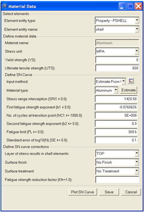
Figure 10: Material data definition
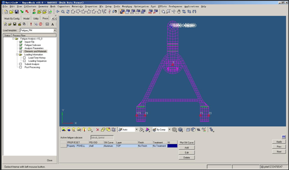
Figure 11: Elements and material definition
Step 6: Load-Time History Definition
| 1. | Make sure the task Load-Time History is selected in the Fatigue Analysis tree. |
| 2. | Click Add by File. A Load Time History window opens. |
| 3. | For Load-time history name, enter lth1. |
| 4. | For Load-time history type, select CSV. |
| 5. | Click the Open load-time file icon  . An Open file browser window opens. . An Open file browser window opens. |
| 8. | Click Save to write the new load-time history into HyperMesh database. |
| 9. | Follow Steps 2 - 8 to create another load-time history lth2 by importing the file load2.csv. |
| 10. | Click Plot L-T to show the load-time history. |
| 11. | Close the Load Time History window. |
| 12. | Click Apply. This saves the current definitions and guides you to the next task Loading Sequences of the Fatigue Analysis tree. |
| Note: | For a file of DAC format, it can very easily be imported in Altair HyperGraph and converted to CSV format for use by FPM. |
|
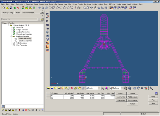
Figure 12: Load-time history definition
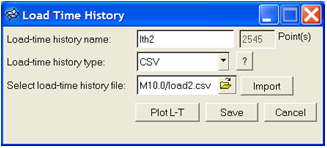
Figure 13: Import load-time history
Step 7: Loading Sequences Definition
In this step, one event consisting of two load time history is created; in other words, the linear superposition of the stress caused by the two load time history is requested during analysis. Using this event, one load sequence is constructed.
| 1. | Make sure the task Loading Sequences is selected in the Fatigue Analysis tree. |
| 2. | Click Add. A Loading Definition window opens. |
| 3. | For Select static loadcase, select SUBCASE1. |
| 4. | For Select load-time history, select lth1. |
| 5. | For Scale, enter the value 3.0. |
| 6. | Make sure Create new is selected using the radio buttons. |
| 7. | Enter Event1 for the newly created fatigue event name. |
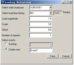
Figure 14: Associate load-time history with static subcase
| 8. | Click Save > Add. A Loading Definition window opens. |
| 9. | For Select static loadcase, select SUBCASE2. |
| 10. | For Select load-time history, select lth2. |
| 11. | Enter the value 3.0 for Scale. |
| 12. | Make sure Existing is selected using the radio buttons. For Existing, select Event1. |
| 13. | Click Save > Apply. This saves the current definitions and guides you to the next task Submit analysis of the Fatigue Analysis tree. |
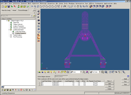
Figure 15: Loading sequences definition
Step 8: Submit fatigue analysis
| 1. | Make sure the task Submit Analysis is selected in the Fatigue Analysis tree. |
| 2. | Click the Save .fem file icon  . A Save As browser window opens. . A Save As browser window opens. |
| 3. | Set the directory in which to save the file, and for File name, enter ctrlarm_fpmtut.fem. |
| 4. | Click Save to close the window. |
| 5. | Click Save to save the OptiStruct model file. |
| 6. | For Run Option, select analysis. |
| 7. | Click Submit. This launches OptiStruct 2017 to run the fatigue analysis. |
If the job was successful, new results files can be seen in the directory where the OptiStruct model file was written.
The default files written to your directory are:
ctrlarm_fpmtut.0.3.fat
|
An ASCII format file which contains fatigue results of each fatigue subcase in iteration step.
|
ctrlarm_fpmtut.h3d
|
Hyper 3D binary results file, with both static analysis results and fatigue analysis results.
|
ctrlarm_fpmtut.out
|
OptiStruct output file containing specific information on the file set up, the set up of your fatigue problem, compute time information, etc. Review this file for warnings and errors.
|
ctrlarm_fpmtut.stat
|
Summary of analysis process, providing CPU information for each step during analysis process.
|
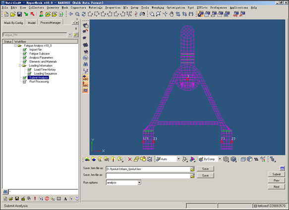
Figure 16: Submit fatigue analysis
Step 9: Post-processing
| 1. | Make sure the task Post-processing is selected in the Fatigue Analysis tree. |
When fatigue analysis has completed successfully after the previous submit, it will automatically go into this task.
| 2. | View the Results type: Life |
Check the top 0.1%, 1.0%, 5.0% average life, and Top 1, 2, 3 most damage elements lives.
| 3. | Toggle the Result type to view the damage results summary. |
| 4. | Click Load H3D Results (HV). This launches HyperView to load the ctrlarm_fpmtut.h3d results file for more detailed results. |
| 5. | Click Close to unload Fatigue Process Manager. |
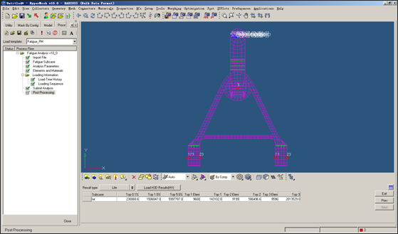
Figure 17: Life results summary
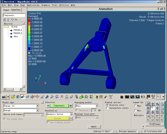
Figure 18: Damage contour in HyperView
See Also:
OptiStruct Tutorials


