This tutorial demonstrates how to simulate a rubber gasket in sequential loading, given the following load sequence:
| • | Translation Transverse (10 mm) |
| • | Translation Longitudinal (5 mm) |
Model Description
| • | UNITS: Length (mm), Time (ms), Mass (kg), Force (kN) and Stress (GPa) |
| o | Engine [0 – 1.501] in steps of 0.5 ms for each load case |
| • | The outer circumference area is fixed on all degrees of freedom (VX, VY, VZ) and the center node is fixed on X direction and the X and Y rotation (VX, WX, Wy) |
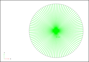
| • | The gasket dimensions are: Thickness = 100 mm, External Diameter = 200 mm and Internal Diameter = 50 mm. |
| • | Hyper-Elastic Material /MAT/LAW42 (Rubber) |
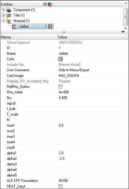
[Rho_I] Initial density = 6.0-6 Kg/mm3
[nu] Poisson’s ratio = 0.495
[mue1] ( 1) = 0.6 1) = 0.6
[alfa1] ( 1) = 2 1) = 2
(alfa2] (2) = -2
|
Exercise
Step 1: Load the RADIOSS (Block) User Profile
| 1. | Launch HyperMesh Desktop. |
| 2. | From the Preferences menu, select the User Profiles or click the  icon in toolbar. icon in toolbar. |
| 3. | Select RADIOSS (Block140) and click OK. |
Step 2: Load the gasket.hm file
| 1. | From the toolbar, click the Open Model icon  to open the gasket.hm file you saved to your working directory from the radioss.zip file. Refer to Accessing the Model Files. to open the gasket.hm file you saved to your working directory from the radioss.zip file. Refer to Accessing the Model Files. |
| 2. | Click Open. The model loads into the graphics area. |
Step 3: Define and assign material, property to Rubber
| 1. | In the Model browser, right-click and select Create > Material to create material. |
| 2. | For Name, enter rubber. |
| 3. | For Card Image, select M42_OGDEN and click Yes in the confirmation window. |
| 4. | Input the values, as shown below: |
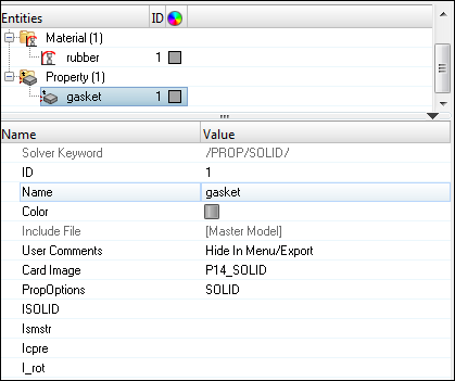
| 5. | In the Model browser, right-click and select Create > Property to create property. |
| 6. | For Name, enter gasket. |
| 7. | For Card Image, select P14_SOLID and click Yes to confirm. |
| 8. | In the Model browser, expand the Component folder and select GASKET. Right-click and Assign (or use the Entity Editor) the newly created property and material. |
Step 4: Create a component for the rigid body at center of Gasket
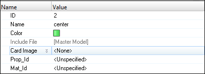
| 1. | In the Model browser, right-click and select Create > Component. |
| 2. | For Name, enter center and switch Card Image to None and click Yes to confirm. |
| 3. | Select any color for easy visualization. |
Step 5: Create a rigid body at center of Gasket
| 1. | From the 1D page, select the rigids panel. |
| 2. | For primary node, switch to calculate node. |
| 3. | For nodes 2-n, switch to multiple nodes. |
| 4. | Click the nodes and select a node in the inner face. |
| 5. | Click nodes and select by face. HyperMesh will select all nodes on the inner face. |
| 7. | Click return to exit the panel. |
Step 6: Create gasket inner fixed boundary conditions
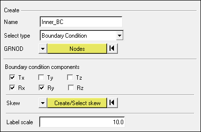
| 1. | From the Utility page, start the BCs Manager. |
| 2. | For Name, enter Inner_BC, set Select type to Boundary Condition and set the GRNOD to Nodes. |
| 3. | Select the master node of rigid body created in Step 5 and click proceed. |
| 4. | Check the Tx translational and Rx, Ry rotational degrees of freedom. |
| 5. | Click Create to create the inner fixed boundary condition. |
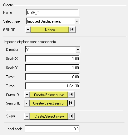
Step 7: Create gasket inner Y displacement boundary conditions
| 1. | From the Utility page, start the BCs Manager. |
| 2. | For Name, enter DISP_Y, set Select type to Imposed Displacement and set the GRNOD to Nodes. |
| 3. | Select the master node of rigid body created in Step 5. |
| 5. | Click Create/Select curve to go to the XY curve editor. |
| 6. | Click New and enter Name as DISP_Y. Click proceed. |
| 7. | Enter the following values for X and Y: |
X = {0, 0.5, 1.0}
Y = {0, 10, 10}
| 8. | Click Update and Close the XY curve editor GUI. |
| 9. | Click Create to create the boundary condition. |
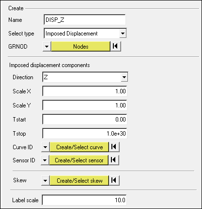
Step 8: Create gasket inner Z displacement boundary conditions
| 1. | From the Utility page, start the BCs Manager. |
| 2. | For Name, enter DISP_Z, set Select type to Imposed Displacement and set the GRNOD to Nodes. |
| 3. | Select the master node of rigid body created in Step 5. |
| 5. | Click Create/Select curve to go to the XY curve editor. |
| 6. | Click New and enter Name as DISP_Z. Click proceed. |
| 7. | Enter the following vales for X and Y: |
X = {0, 0.5, 1, 1.5}
Y = {0, 0, 5, 5}
| 8. | Click Update and Close the XY curve editor GUI. |
| 9. | Click Create to create the boundary condition. |
Step 9: Create gasket inner Z rotation boundary conditions
| 1. | From the Utility page, start the BCs Manager. |
| 2. | For Name, enter ROT20DEG_Z, set Select type to Imposed Displacement and set the GRNOD to Nodes. |
| 3. | Select the master node of rigid body created in Step 5. |
| 5. | Click Create/Select curve to go to the XY curve editor. |
| 6. | Click New and enter Name as ROT20DEG_Z. Click proceed. |
| 7. | Enter the following vales for X and Y: |
X = {0, 1, 1.5, 2}
Y = {0, 0, 0.349, 0.349}
| 8. | Click Update and Close the XY curve editor GUI. |
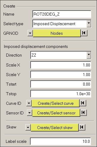
| 9. | Click Create to create the boundary condition. |
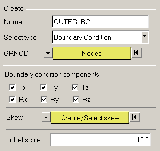
Step 10: Create gasket outer boundary conditions
| 1. | From the Utility page, start the BCs Manager. |
| 2. | For Name, enter OUTER_BC, set Select type to Boundary Condition and set the GRNOD to Nodes. |
| 3. | Click Nodes and select a node on the outer surface. |
| 4. | Click Nodes on the panel and then select by face to select all nodes on the outer surface. |
| 5. | Check all the translational and rotational degrees of freedom. |
| 6. | Click Create to create the outer fixed boundary condition. |
Step 11: Create output request and control cards
| 1. | Launch the HyperMesh Solver browser from View > Browsers > HyperMesh > Solver. |
| 2. | Right-click in the Solver browser general area to create the cards shown below with the given values for each parameter: |
Keyword Type
|
Keyword
|
Parameter
|
Parameter Value
|
CONTROL CARDS
|
TITLE
|
Status
|
[Checked]
|
CONTROL CARDS
|
TITLE
|
TITLE
|
GASKET
|
CONTROL CARDS
|
MEMORY
|
Status
|
[Checked]
|
CONTROL CARDS
|
MEMORY
|
NMOTS
|
40000 Not needed
|
CONTROL CARDS
|
SPMD
|
Status
|
[Checked]
|
CONTROL CARDS
|
IOFLAG
|
Status
|
[Checked]
|
CONTROL CARDS
|
ANALY
|
Status
|
[Checked]
|
ALE-CFD-SPH
|
ALE_CFD_SPH_CARD
|
Status
|
[Checked]
|
ALE-CFD-SPH
|
ALE_CFD_SPH_CARD
|
ALE_Grid_Velocity
|
[Checked]
|
ALE-CFD-SPH
|
ALE_CFD_SPH_CARD
|
GridVel_Gamma
|
100.00
|
ENGINE KEYWORDS
|
RUN
|
Status
|
[Checked]
|
ENGINE KEYWORDS
|
RUN
|
RunName
|
GASKET
|
ENGINE KEYWORDS
|
RUN
|
Tstop
|
1.51
|
ENGINE KEYWORDS
|
PARITH
|
Status
|
[Checked]
|
ENGINE KEYWORDS
|
PARITH
|
Keyword2
|
ON
|
ENGINE KEYWORDS
|
PRINT
|
Status
|
[Checked]
|
ENGINE KEYWORDS
|
PRINT
|
N_Print
|
-1000
|
ENGINE KEYWORDS
|
ANIM/ELEM
|
Status
|
[Checked]
|
ENGINE KEYWORDS
|
ANIM/ELEM
|
VONM
|
[Checked]
|
ENGINE KEYWORDS
|
ANIM/ELEM
|
DENS
|
[Checked]
|
ENGINE KEYWORDS
|
ANIM/ELEM
|
PRES
|
[Checked]
|
ENGINE KEYWORDS
|
ANIM/VECT
|
Status
|
[Checked]
|
ENGINE KEYWORDS
|
ANIM/VECT
|
CONT
|
[Checked]
|
ENGINE KEYWORDS
|
ANIM/DT
|
Status
|
[Checked]
|
ENGINE KEYWORDS
|
ANIM/DT
|
Tstart
|
0
|
ENGINE KEYWORDS
|
ANIM/DT
|
Tfreq
|
0.05
|
ENGINE KEYWORDS
|
DT
|
Status
|
[Checked]
|
ENGINE KEYWORDS
|
DT
|
Tscale
|
0.0
|
ENGINE KEYWORDS
|
DT
|
Tmin
|
0.0
|
ENGINE KEYWORDS
|
TFILE
|
Time frequency
|
1.5e-3
|
Step 12: Export the model
| 1. | Click File > Export or click the Export icon  . . |
| 2. | For File:, navigate to the destination directory where you want to export to. |
| 3. | For name, enter GASKET and click Save. |
| 4. | Click the downward-pointing arrows next to Export options to expand the panel. |
| 5. | Click Merge starter and engine file to export solver deck as one file (or export separately). |
| 6. | Click on Export to export solver deck. |
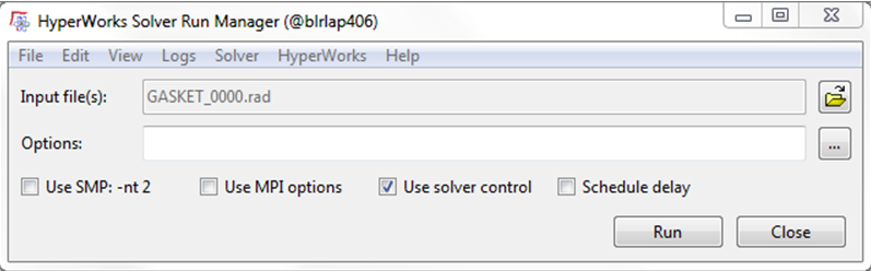
Step 13: Open RADIOSS Manager from windows Start menu
| 1. | Go to Start > Programs > Altair HyperWorks 14.0 > RADIOSS. |
| 2. | For Input file, browse to the exercise folder and select the file GASKET_0000.rad. |
Step 14: Review the listing files for this run and verify on the results
| 1. | See if there are any warnings or errors in .out files. |
| 2. | Using HyperView plot the displacement and strain contour and vectors. |
Exercise Expected Results
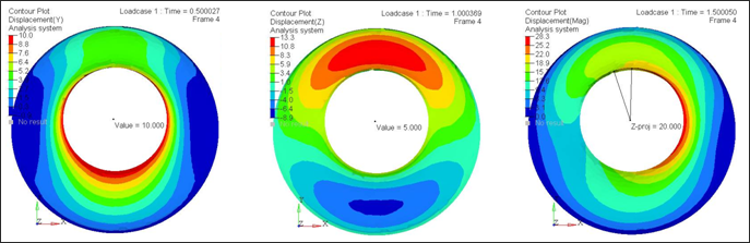
Displacement Contour for the 3 load steps (mm)
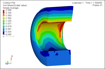
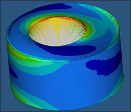
Von Mises Stress Contour at the end of the simulation
See Also:
RADIOSS Tutorials


