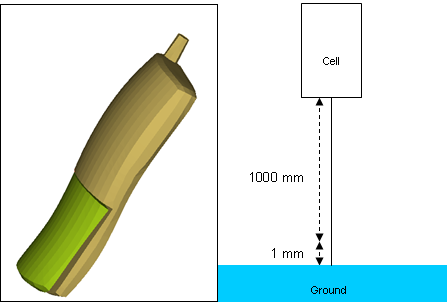
This tutorial demonstrates how to simulate a free fall of a cell phone due to gravity from a height of 1001mm using 2nd order tetra elements.
Model Description
| • | UNITS: Length (mm), Time (s), Mass (ton), Force (N) and Stress (MPa) |
| • | Simulation time: in Engine [0 – 3.3e-3] |
| • | This is a very simple cell phone model used to demonstrate how to set up a drop test. The model is an assembly of two solid parts meshed with Tetra 10 elements, connected with spring elements, and contact defined between them. |
| • | To reduce the simulation time, the cell phone is dropped 1 mm from the ground with an initial velocity of -4429.4469 mm/s representing the velocity that it would have attained from a free fall of 1000 mm. |
| • | Boundary Conditions: Gravity load + initial velocity of -4429.4469 mm/s on the cell phone. |
| • | Elasto-plastic Material /MAT/LAW36 (Plastic) |
[Rho_I] Initial density = 1.16E-9 ton/mm3
[nu] Poisson's ratio = 0.3
[E] Young's modulus = 1000 MPa
|
Exercise
Step 1: Load the RADIOSS User Profile
| 1. | Launch HyperMesh Desktop. |
| 2. | From the Preferences menu, select the User Profiles or click the  icon in toolbar. icon in toolbar. |
| 3. | Select RADIOSS (Block140) and click OK. |
Step 2: Load the cellphone.hm file
| 1. | From the toolbar, click the Open Model icon  to open the cellphone.hm file you saved to your working directory from the radioss.zip file. Refer to Accessing the Model Files. to open the cellphone.hm file you saved to your working directory from the radioss.zip file. Refer to Accessing the Model Files. |
| 2. | Click Open. The model loads into the graphics area. |
Step 3: Creating the material curve
| 1. | Click XYPlots > Curve Editor. |
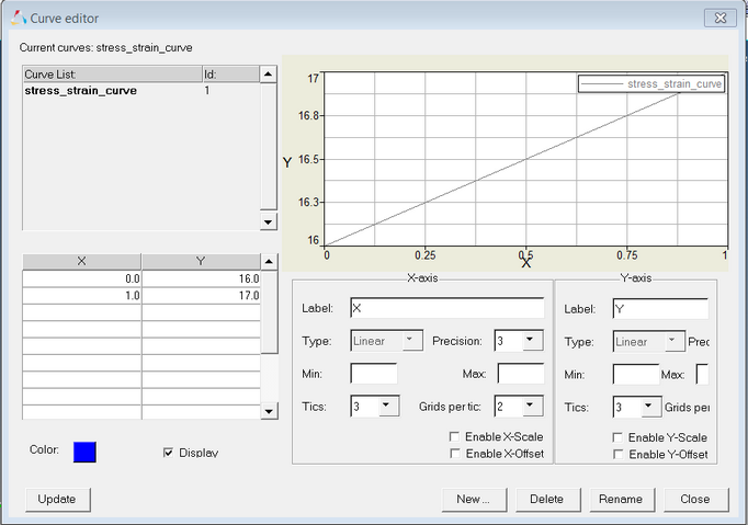
| 2. | In the Curve editor window, click New. |
| 3. | For the curve name, enter stress_strain_curve. |
| 5. | From the Curve editor window, select stress_strain_curve from the Curve List. |
| 6. | Enter the X and Y coordinates, as shown below. |
Step 4: Create material and properties for the cell phone parts
| 1. | In the Model browser, right-click and select Create > Material to create a new material. |
| 2. | For Name, enter cell_phone. |
| 3. | For Card Image, select M36_PLAS_TAB and click Yes in the confirmation window. |
| 4. | Input the values, as shown below. |
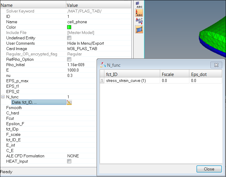
| 5. | Select N_func and set to 1. |
| 6. | Click fct_ID1 and select stress_strain_curve (the function curve previously created). |
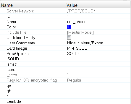
| 7. | In the Model browser, right-click and select Create > Property to create a property. |
| 8. | For Name, enter cell_phone. |
| 9. | For Card Image, select P14_SOLID and click Yes to confirm. |
| 10. | Set the variable I_tetra to a value of 1. |
| 11. | In the Model browser, expand the Components folder and highlight the components Cellphone_bottom and Cellphone_top and right-click to Assign (or use the Entity Editor) the newly created property and material. |
Step 5: Create property for the spring links
| 1. | In the Model browser, right-click and select Create > Property to create a new property. |
| 2. | For Name, enter spring. |
| 3. | Set Card Image to P13_SPR_BEAM and click Yes to confirm. |
| 4. | Enter the following values: |
Mass (MASS): 2e-6 ton
Inertia (Inertia): 2e-4 mm4
Translation stiffness (K_Tensn, K_ShrY, and K_ShrZ): 50
Rotation stiffness (K_Tor, K_FlxY, and K_FlxZ): 100N
| 5. | Click return to return to component panel. |
| 6. | In the Model browser, select the component Connection_springs and right-click Assign (or use the Entity Editor) to assign the newly created property to the spring component. |
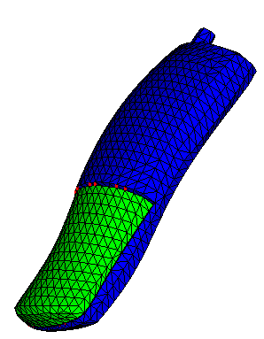
Step 6: Define the Interface between cell phone parts
| 1. | In the Model browser, right-click and select Create > Contact Surface. |
| 4. | Switch from add shell elements to add solid faces. |
| 5. | Select elements by collector and select Cellphone_bottom and click select. |
| 6. | For face nodes, select nodes by collector and select cellphone bottom and click select > add > return. |
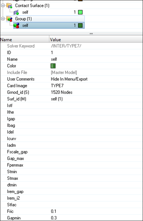
| 7. | In the Model browser, right-click and select Create > Contact. |
| 9. | Set Card Image to TYPE7 and click Yes to confirm. |
| 10. | For Grnod_id (S), select nodes > by collector and select Cellphone_top and click select > add and click return. |
| 11. | For Surf_id (M), switch to Contactsurf, click on Contactsurf and select self. |
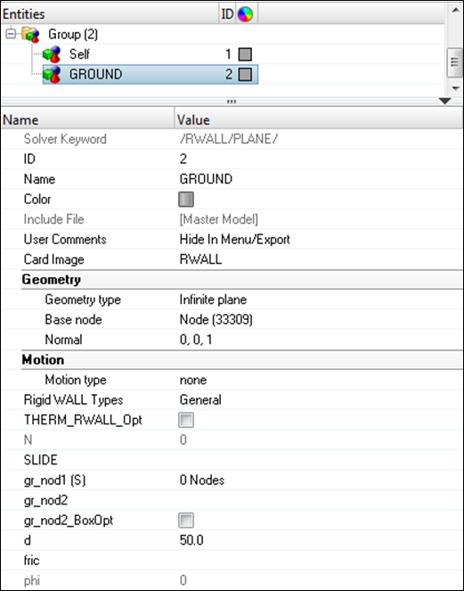
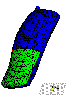
Step 7: Create a rigid wall
| 1. | In the Model browser, right-click and select Create > Rigid Wall. |
| 2. | For Name, enter GROUND. |
| 3. | Set the Geometry type to Infinite plane. |
| 4. | Click in the graphics area and press the F8 key on the keyboard. Enter the node coordinates: X=0, Y=0, and Z=19. |
| 6. | Click return to exit the panel. |
| 7. | In the Entity Editor, select the created node as Base node. |
| 8. | Make sure the normal vector is set to z-axis, as shown below. |
| 10. | To review, go to the Solver browser, select the RWALL folder. |
| 11. | Right-click on GROUND and click Review. |
| 12. | Click return to exit from the panel. |
Step 8: Define gravity load
| 1. | In the Model browser, right-click and select Create > Set. |
| 2. | For Name, enter Gravity, set Card Image as GRNOD and click Yes to confirm. |
| 3. | Select Nodes of all three parts. |
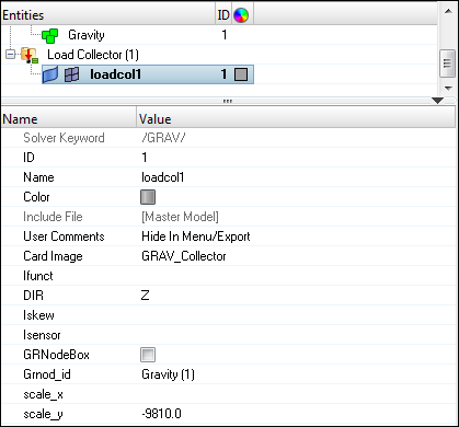
| 4. | In the Model browser, right-click and select Create > Load Collector. |
| 5. | For Name, enter loadcol1, set Card Image as GRAV_Collector and click Yes to confirm. |
| 7. | For Grnod_id, select Gravity from the Select Set dialog and click OK. |
| 8. | Set scale_y to -9810.0 indicating gravity in opposite Z direction. |
| 9. | From the XYPlots pull-down, click Curve Editor. |
| 10. | In the Curve editor window, click New. |
| 11. | For Name =, enter gravity. |
| 13. | In the Curve editor window, select gravity from the Curve List. |
| 14. | Enter X and Y, as shown in the following image: |
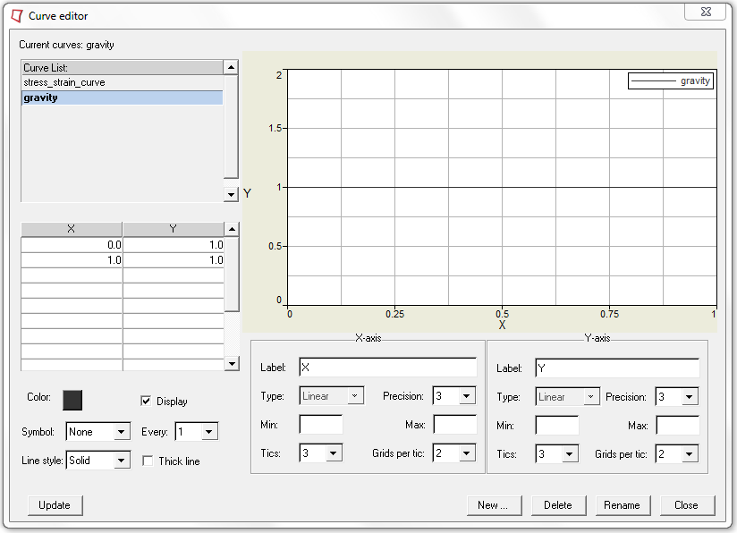
| 15. | Click Update > Close to close the Curve editor window. |
| 16. | Back in Gravity load collector, update Ifunc to the curve just created. |
Step 9: Apply an initial velocity to the Cell Phone
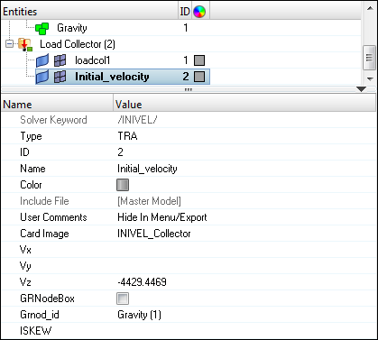
| 1. | In the Model browser, right-click and select Create > Load Collector. |
| 2. | For Name, enter Initial_velocity, set Card Image to INIVEL_Collector. |
| 3. | For Grnod_id, select the same set (Gravity) previously used. |
| 4. | For Vz =, enter the value -4429.4469. |
Step 10: Creating output request and control cards
| 1. | Launch the HyperMesh Solver browser from View > Browsers > HyperMesh > Solver. |
| 2. | Right-click in the Solver browser general area to create the cards shown below with the given values for each parameter: |
Keyword Type
|
Keyword
|
Parameter
|
Parameter Value
|
CONTROL CARDS
|
TITLE
|
Status
|
[Checked]
|
CONTROL CARDS
|
TITLE
|
TITLE
|
Cellphone_drop
|
CONTROL CARDS
|
MEMORY
|
Status
|
[Checked]
|
CONTROL CARDS
|
MEMORY
|
NMOTS
|
40000 Not needed
|
CONTROL CARDS
|
SPMD
|
Status
|
[Checked]
|
CONTROL CARDS
|
IOFLAG
|
Status
|
[Checked]
|
CONTROL CARDS
|
ANALY
|
Status
|
[Checked]
|
ALE-CFD-SPH
|
ALE_CFD_SPH_CARD
|
Status
|
[Checked]
|
ALE-CFD-SPH
|
ALE_CFD_SPH_CARD
|
ALE_Grid_Velocity
|
[Checked]
|
ALE-CFD-SPH
|
ALE_CFD_SPH_CARD
|
GridVel_Gamma
|
100.00
|
ENGINE KEYWORDS
|
RUN
|
Status
|
[Checked]
|
ENGINE KEYWORDS
|
RUN
|
Tstop
|
3e-3
|
ENGINE KEYWORDS
|
PARITH
|
Status
|
[Checked]
|
ENGINE KEYWORDS
|
PARITH
|
Keyword2
|
ON
|
ENGINE KEYWORDS
|
PRINT
|
Status
|
[Checked]
|
ENGINE KEYWORDS
|
PRINT
|
N_Print
|
-1000
|
ENGINE KEYWORDS
|
ANIM/ELEM
|
Status
|
[Checked]
|
ENGINE KEYWORDS
|
ANIM/ELEM
|
VONM
|
[Checked]
|
ENGINE KEYWORDS
|
ANIM/ELEM
|
DENS
|
[Checked]
|
ENGINE KEYWORDS
|
ANIM/ELEM
|
PRES
|
[Checked]
|
ENGINE KEYWORDS
|
ANIM/ELEM
|
EPSP
|
[Checked]
|
ENGINE KEYWORDS
|
ANIM/VECT
|
Status
|
[Checked]
|
ENGINE KEYWORDS
|
ANIM/VECT
|
CONT
|
[Checked]
|
ENGINE KEYWORDS
|
ANIM/DT
|
Status
|
[Checked]
|
ENGINE KEYWORDS
|
ANIM/DT
|
Tstart
|
0.0
|
ENGINE KEYWORDS
|
ANIM/DT
|
Tfreq
|
2e-4
|
ENGINE KEYWORDS
|
DT
|
Status
|
[Checked]
|
ENGINE KEYWORDS
|
DT
|
Tscale
|
0.0
|
ENGINE KEYWORDS
|
DT
|
Tmin
|
0.0
|
Step 11: Export the model
| 1. | Click File > Export or click the Export Solver Deck icon  . . |
| 2. | For File:, navigate to the destination directory where you want to export to. |
| 3. | For Name, enter Cellphone and click Save. |
| 4. | Click the downward-pointing arrows next to Export options to expand the panel. |
| 5. | Click Merge starter and engine file to export solver deck as one file (or export separately). |
| 6. | Click on Export to export solver deck. |
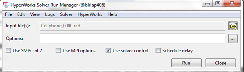
Step 12: Open RADIOSS Manager from windows Start menu
| 1. | Go to Start > Programs > Altair HyperWorks 14.0 > RADIOSS. |
| 2. | For Input file(s), browse to the exercise folder and select the file cellphone_0000.rad. |
Step 13: Review the listing files for this run and verify on the results
| 1. | See if there are any warnings or errors in .out files. |
| 2. | Using HyperView plot the strain and stress contour. |
Exercise Expected Results
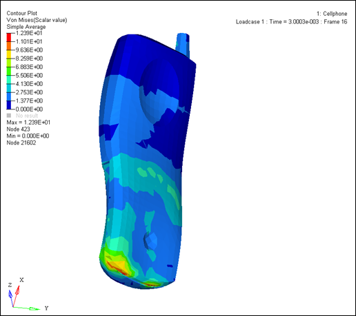
Von Mises Stress Contour (MPa)
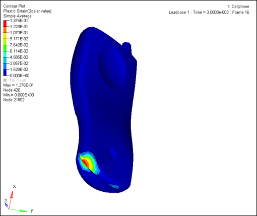
Plastic Strain (mm/mm)
See Also:
RADIOSS Tutorials


