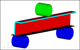
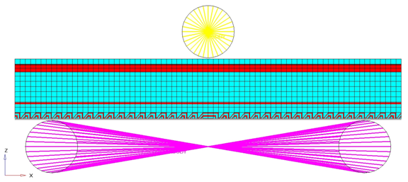
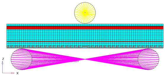
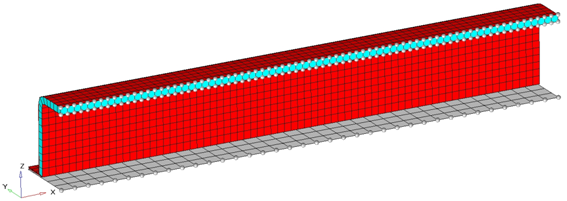
This tutorial demonstrates how to set up 3-point bending model with symmetric boundary conditions in Y direction.
Model Description
| • | UNITS: Length (mm), Time (s), Mass (ton), Force (N) and Stress (MPa) |
| • | Simulation time: in Engine file [0 – 6.601e-002 s] |
| • | Only one half of the model is modeled because it is symmetric. |
| • | The supports are totally fixed. An imposed velocity of 1000 mm/s is applied on the Impactor in the (–Z) direction |
| • | Model size = 370mm x 46.5mm x 159mm |
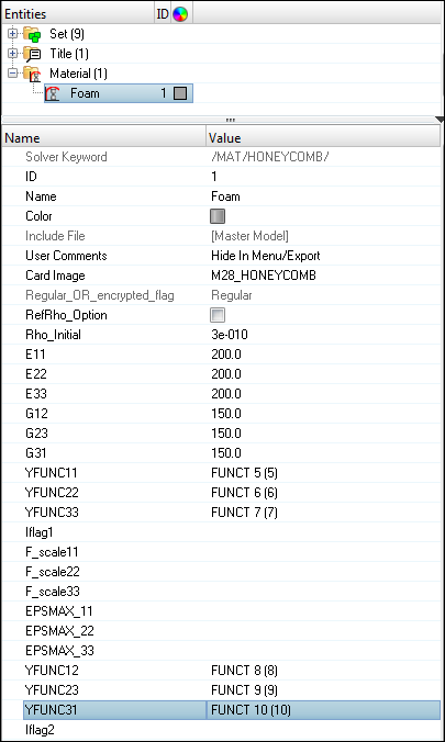
| • | Honeycomb Material /MAT/LAW28: HONEYCOMB |
[Rho_I] Initial density = 3.0e-10 ton/mm3
[E11], [E22] and [E33] Young’s modulus (Eij) = 200 MPa
[G11], [G22] and [G33] Shear modulus (Gij) = 150 MPa
|
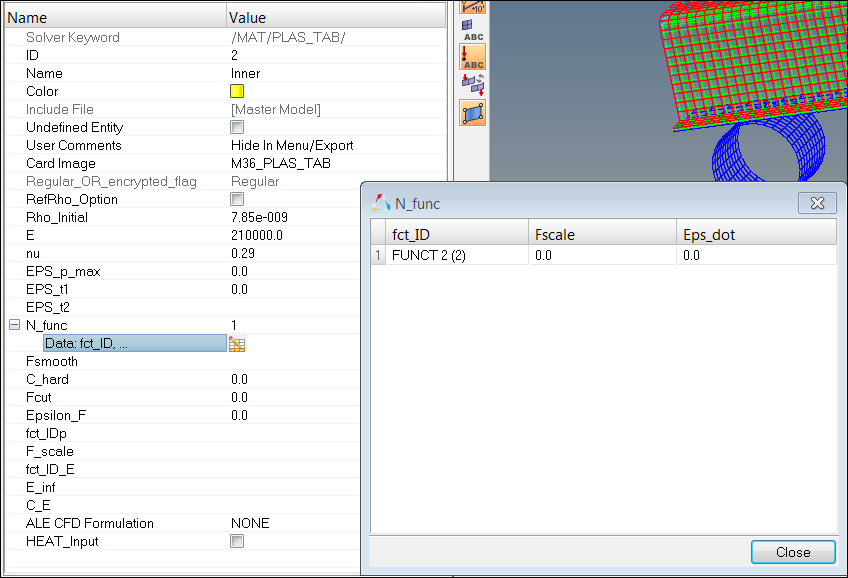
| • | Elasto-Plastic Material /MAT/LAW36: Inner, Outer and Flat |
[Rho_I] Initial density = 7.85-9 ton/mm3
[E] Young’s modulus = 210000 MPa
[nu] Poisson's ratio = 0.29
|
|
0
|
1
|
2
|
3
|
4
|
5
|
6
|
7
|
8
|
9
|
STRAIN
|
0
|
0.012002
|
0.014003
|
0.018003
|
0.022002
|
0.026003
|
0.030006
|
0.032
|
0.033005
|
0.033523
|
STRESS
|
325
|
335.968
|
343783
|
349.245
|
358.649
|
372.309
|
383.925
|
388.109
|
389.292
|
389.506
|
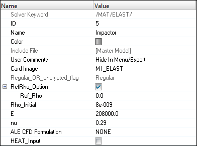
| • | Elastic Material /MAT/PLAS_JOHNS: Impactor |
[Rho_I] Initial density = 8e-9 ton/mm3
[E] Young’s modulus = 208000 MPa
[nu] Poisson's ratio = 0.29
|
Exercise
Step 1: Load the RADIOSS User Profile
| 1. | Launch HyperMesh Desktop. |
| 2. | From the Preferences menu, select the User Profiles or click the  icon in toolbar. icon in toolbar. |
| 3. | Select RADIOSS (Block140) and click OK. |
Step 2: Retrieve the RADIOSS file
| 1. | Click File > Import > Solver Deck or click  . . |
| 2. | Click the Select File icon  to open the BENDING_0000.rad file you saved to your working directory from the radioss.zip file. Refer to Accessing the Model Files. to open the BENDING_0000.rad file you saved to your working directory from the radioss.zip file. Refer to Accessing the Model Files. |
| 4. | Click Close to close the window. |
Step 3: Create and Assign material and property for HCFOAM
| 1. | In the Model browser, right-click and select Create > Material. The new material appears in the Entity Editor. |
| 3. | For Card Image, select M28_HONEYCOMB and click Yes to confirm. |
| 4. | Input values, as shown below: |
| 5. | In the Model browser, right-click and select Create > Property to create a new property. |
| 6. | For Name, enter Foam and set the new property Card Image as P14_SOLID. Leave all the settings as default, except for ISOLID which should be set to 24. |
| 7. | In the Model browser, right-click on the component HCFoam and select Assign. Assign Foam as the Prop_Id and Foam as the Mat_Id. |
Step 4: Create and Assign material and property for the component Inner
| 1. | In the Model browser, right-click and select Create > Material. The new material appears in the Entity Editor. |
| 3. | For Card Image, select M36_PLAS_TAB and click Yes to confirm. |
| 4. | Input the values, as shown below: |
| 5. | In the Model browser, right-click and select Create > Property to create a new property. |
| 6. | For Name, enter Inner and set Card Image as P1_SHELL. Leave all the settings as default, except for Ishell which should be set to 4 and Thick which should be set to 9.119e-01. |
| 7. | In the Model browser, right-click on the component Inner and select Assign. Assign Inner as the Prop_Id and Inner as the Mat_Id. |
Step 5: Create and Assign material and property for the component Outer
| 1. | In the Model browser, right-click on the material Inner and select Duplicate. Name the new material Outer. This creates a new material that is identical to the source material. |
| 2. | In the Model browser, right-click on the property Inner and select Duplicate. Name the new property Outer. This creates a new property that is identical to the source property. |
| 3. | In the Model browser, right-click on the component Outer and select Assign. Assign Outer as the Prop_Id and Outer as the Mat_Id. |
Step 6: Create and Assign material and property for the component Flat
Follow the procedure described in Step 5 with Outer replaced by Flat.
Step 7: Create and assign material and property for Impactor
| 1. | In the Model browser, right-click and select Create > Material. The new material shows up in the Entity Editor. |
| 2. | For Name, enter Impactor. |
| 3. | For Card Image, select M1_ELAST. |
| 4. | Input the values, as shown below: |
| 5. | In the Model browser, right-click on the property Inner and select Duplicate. Name the new property Impactor. This creates a new property that is identical to the source property. |
| 6. | In the Model browser, right-click on the component Impactor and select Assign. Assign Impactor as the Prop_Id and Impactor as the Mat_Id. |
Step 8: Create and assign material and property for Support
Follow the same procedures as in Step 5. Create a copy of Impactor property and material with name support and assign it to component support.
Step 9: Create a rigid body to make Impactor and Support Rigid
| 1. | In the Model browser, right-click and select Create > Component. |
| 2. | For Name, enter Impact rigid. |
| 3. | Select any color for easy visualization. |
| 4. | Set Card Image to None. |
| 5. | Go to the 1D page, select the rigids panel. |
| 6. | Verify that you are in the create subpanel. |
| 7. | For dependent switch to comps. |
| 8. | For primary node switch to calculate node. |
| 10. | Select Impactor, then click select. |
| 12. | Click return to exit the panel. |
| 13. | Similarly, create rigid body for Support component in a collector with the name “Support rigid” using Steps 9.1 to 9.12. |
Step 10: Define imposed velocity and boundary condition for the impactor
| 1. | From the Utility page, start the BCs Manager. |
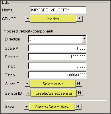
| 2. | For Name, enter IMPOSED_VELOCITY, set Select type to Imposed Velocity and set the GRNOD to Nodes. |
| 3. | Click nodes and select the master node of the rigid body of the Impactor, as shown in the following image. |
| 4. | Set the Direction as Z. |
| 5. | Set Scale Y to -1000.0 as the direction of velocity is opposite to the global Z-axis. |
| 6. | Set the Curve ID to Select curve. |
| 7. | Select the predefined curve to Func1. |
| 8. | Click create to create the imposed velocity. |
| 9. | For Name, enter Impactor_constraints, set Select type to Boundary Condition and set the GRNOD to Nodes. |
| 10. | Click nodes and select the master node of the rigid body. |
| 11. | Check all the degrees of freedom to constrain, except Tz. |
| 12. | Click create to create the boundary condition. |
Step 11: Define fixed boundary condition for the support
| 1. | From the Utility page, start the BCs Manager. |
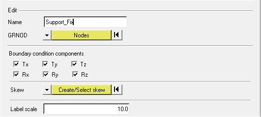
| 2. | For Name, enter Support_fixed, set Select type to Boundary Condition and set the GRNOD to Nodes. |
| 3. | Select the master node of the rigid body created on Supporter, as shown in the following image. |
| 4. | Check all the degrees of freedom. |
| 5. | Click create to create the boundary condition. |
Step 12: Define symmetry boundary condition for the foam, inner, outer and flat
| 1. | From the Utility page, start the BCs Manager. |
| 2. | For Name, enter SYMMETRY_XZ, set Select type to Boundary Condition and set the GRNOD to Nodes. |
| 3. | Select the nodes of the foam, inner, outer and flat, as shown in the following image. |
| 4. | Check the degrees of translational degrees of freedom Y and rotational degrees of freedom X and Z to constraint. |
| 5. | Click create to create the boundary condition. |
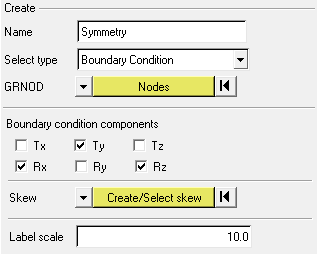
| 6. | Click close to exit the BC Manager. |
Step 13: Define contacts between the beam and the support
| 1. | Launch the HyperMesh Solver browser from View > Browsers > HyperMesh > Solver. |
| 2. | In the Solver browser, right-click and select Create > INTER > TYPE7. |
| 3. | Enter the values, as shown below: |
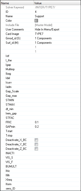
| 4. | Set the Surf_id (M) for the master selection to Components and select the Support component. |
| 5. | Set the Grnod_id (S) for the slave selection to Components and select the Flat component. |
| 6. | Similarly create the contact for Impactor with Outer, as shown below. |

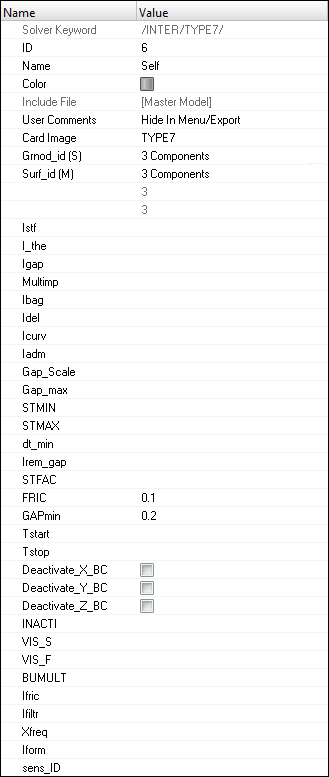
Step 14: Define the self contact between the beam components
| 1. | Using the directions in Step 13, create a new Type 7 interface named Self with the components Outer, Inner, and Flat as Master and the same components Outer, Inner, and Flat as Slave. This will make the components self-contact instead of self-penetrate. Verify that the interface has a Fric of 0.1 and Gapmin of 0.2. |
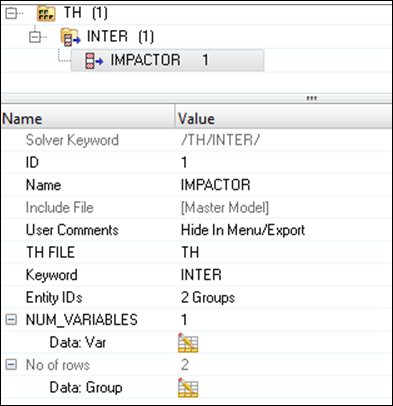
Step 15: Create Interface time history
| 1. | Right-click in the Solver browser and select Create > TH > INTER. |
| 2. | For Name, enter IMPACTOR. |
| 3. | Switch the entity selector to groups. |
| 4. | Click groups and select the interfaces Impactor and Support from the list. |
| 6. | Set NUM_VARIABLES to 1 and Data: Var to DEF. |
Step 16: Creating control cards and output requests
| 1. | Launch the HyperMesh Solver browser from View > Browsers > HyperMesh > Solver. |
| 2. | Right-click in the Solver browser general area to create the cards shown below with the given values for each parameter: |
Keyword Type
|
Keyword
|
Parameter
|
Parameter Value
|
CONTROL CARDS
|
TITLE
|
Status
|
[Checked]
|
CONTROL CARDS
|
TITLE
|
TITLE
|
3PBENDING
|
ENGINE KEYWORDS
|
RUN
|
Status
|
[Checked]
|
ENGINE KEYWORDS
|
RUN
|
RunName
|
3PBENDING
|
ENGINE KEYWORDS
|
RUN
|
RunNumber
|
1
|
ENGINE KEYWORDS
|
RUN
|
Tstop
|
7.01e-2
|
ENGINE KEYWORDS
|
TFILE
|
Status
|
[Checked]
|
ENGINE KEYWORDS
|
TFILE
|
Time_frequency
|
0.0001
|
ENGINE KEYWORDS
|
PRINT
|
Status
|
[Checked]
|
ENGINE KEYWORDS
|
PRINT
|
N_Print
|
-100
|
ENGINE KEYWORDS
|
ANIM/ELEM
|
Status
|
[Checked]
|
ENGINE KEYWORDS
|
ANIM/ELEM
|
VONM
|
[Checked]
|
ENGINE KEYWORDS
|
ANIM/ELEM
|
EPSP
|
[Checked]
|
ENGINE KEYWORDS
|
ANIM/VECT
|
Status
|
[Checked]
|
ENGINE KEYWORDS
|
ANIM/VECT
|
VEL
|
[Checked]
|
ENGINE KEYWORDS
|
ANIM/VECT
|
CONT
|
[Checked]
|
ENGINE KEYWORDS
|
ANIM/DT
|
Status
|
[Checked]
|
ENGINE KEYWORDS
|
ANIM/DT
|
Tstart
|
0
|
ENGINE KEYWORDS
|
ANIM/DT
|
Tfreq
|
2.5e-3
|
ENGINE KEYWORDS
|
DT
|
Status
|
[Checked]
|
ENGINE KEYWORDS
|
DT
|
Tscale
|
0.0
|
ENGINE KEYWORDS
|
DT
|
Tmin
|
0.0
|
ENGINE KEYWORDS
|
DT/NODA
|
Status
|
[Checked]
|
ENGINE KEYWORDS
|
DT/NODA
|
CST_0
|
[Checked]
|
ENGINE KEYWORDS
|
DT/NODA/CST_0
|
Tscale
|
0.9
|
ENGINE KEYWORDS
|
DT/NODA/CST_0
|
Tmin
|
7e-7
|
ENGINE KEYWORDS
|
DT/NODA
|
DEL
|
[Checked]
|
ENGINE KEYWORDS
|
DT/NODA/DEL
|
Tscale
|
0.9
|
ENGINE KEYWORDS
|
DT/NODA/DEL
|
Tmin
|
3.5e-8
|
ENGINE KEYWORDS
|
RBODY_ENGINE RBODY/ON
|
Status
|
[Checked]
|
ENGINE KEYWORDS
|
RBODY_ENGINE
|
NUM_rbnodes
|
2
|
ENGINE KEYWORDS
|
RBODY_ENGINE
|
Data: Nodes
|
29664
29665
|
Step 17: Export the model
| 1. | Click File > Export or click the Export icon  . . |
| 2. | For File:, navigate to the destination directory where you want to export to. |
| 3. | For name, enter 3BENDING and click Save. |
| 4. | Click the downward-pointing arrows next to Export options to expand the panel. |
| 5. | Click Merge starter and engine file to export solver deck as one file (or export separately). |
| 6. | Click on Export to export solver deck. |
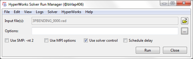
Step 18: Open RADIOSS Manager
| 1. | Go to Start > Programs > Altair HyperWorks 14.0 > RADIOSS. |
| 2. | For Input file, browse to the exercise folder and select the file 3PBENDING_0000.rad. |
Step 19: Review the listing files for this run and verify on the results
| 1. | See if there are any warnings or errors in .out files. |
| 2. | Using HyperView, plot the displacement, strain contour and vectors. |
Exercise Expected Results
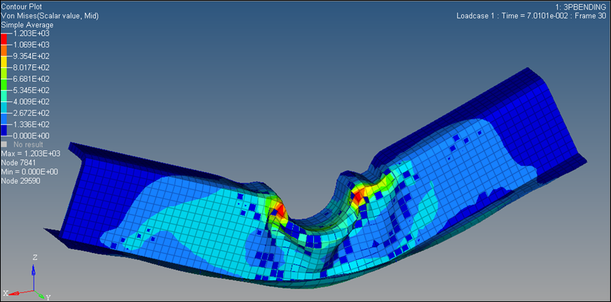
von Mises Stress Contour (MPa)
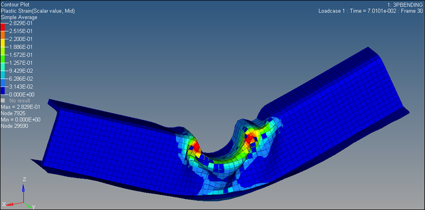
Plastic Strain Contour
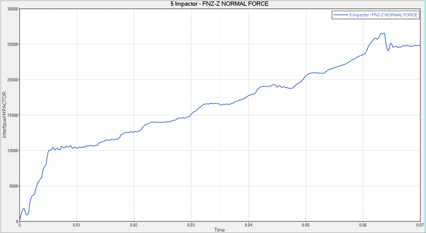
Contact Force for Impactor Interface
See Also:
RADIOSS Tutorials


