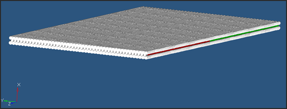
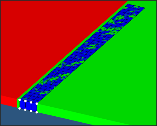
The objective of this tutorial is to simulate the flow of water through a rubber valve using an inlet option in multi-phase material law (Law 51). In this model the top chamber is air, the lower chamber is water, and the bottom row of elements is the inlet. Law 51 is used for air, water and inlet. Boundary conditions are applied on each surface of fluid in its normal direction. An interface between fluid and rubber (CEL) is defined to manage the contact.
Exercise
Step 1: Load the RADIOSS User Profile
| 1. | Launch HyperMesh Desktop. |
| 2. | From the Preferences menu, select the User Profiles or click the  icon in toolbar. icon in toolbar. |
| 3. | Select RADIOSS (Block140) and click OK. |
Step 2: Load the valve.hm file
| 1. | From the toolbar, click the Open Model icon  to open the valve.hm file you saved to your working directory from the radioss.zip file. Refer to Accessing the Model Files. to open the valve.hm file you saved to your working directory from the radioss.zip file. Refer to Accessing the Model Files. |
| 2. | Click Open. The model loads into the graphics area. |
Step 3: Creating curves for pressure_inlet
| 1. | Launch the HyperMesh Solver browser from View > Browsers > HyperMesh > Solver. |
| 2. | In the Solver browser, right-click and select Create > FUNCT. The Curve editor dialog box opens. |
| 3. | In the Curve editor window, click New. |
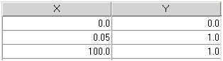
| 4. | For the Name, enter pressure_inlet and click proceed. |
| 5. | From the Curve editor window, select pressure_inlet from the curve list. |
| 6. | Enter the X and Y coordinates, as shown below. |
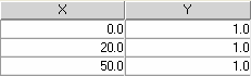
| 8. | Follow Steps 3.3 - 3.7 to create a curve named density, with the values shown below. |
Step 4: Define and assign Material, Property to component inlet
| 1. | In the Model browser, right-click and select Create > Material. The new material appears in the Entity Editor. |
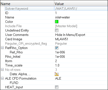
| 2. | For Name, enter inlet-water. |
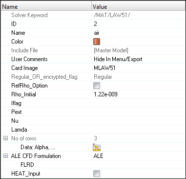
| 3. | For Card Image, select MLAW51 and click Yes to confirm. |
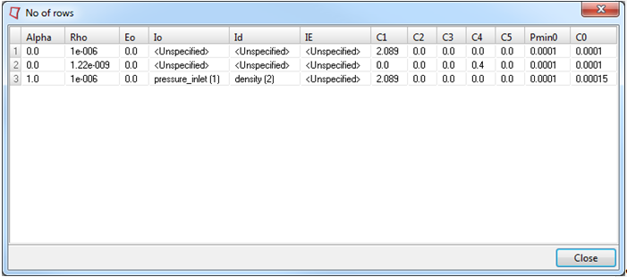
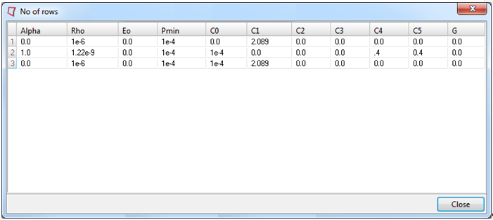
| 4. | Input the values, as shown below: |
Remember to select ALE under ALE CFD Formulation.
| 5. | In the Model browser, right-click and select Create > Property to create a new property. |
| 6. | For Name, enter solids. |
| 7. | For Card Image, select P14_SOLID. Keep all the default settings. |
| 9. | In the Model browser, click on the inlet component and assign solids as the Prop_Id and inlet-water as the Mat_Id. |
Step 5: Define and assign Material, Property to component Air
| 1. | In the Model browser, right-click and select Create > Material. The new material appears in the Entity Editor. |
| 3. | For Card Image, select MLAW51 and click Yes to confirm. |
| 4. | Input the values, as shown below. |
Remember to select ALE under ALE CFD Formulation.
| 5. | Click on the air component in the Model browser and assign solids as the Prop_Id and air as the Mat_Id. |
Step 6: Define and assign Material, Property to component Water
| 1. | In the Model browser, right-click on the material air and click Duplicate. Edit the material parameters and table data with the following changes. |
| 2. | Change the Name to water. |
| 4. | Change the value for Alpha(1) to 1.0 and Alpha(2) to 0.0. |
| 5. | Change Rho_Initial to 1.000e-06. |
| 6. | In the Model browser, right-click on the water component and select Assign. Assign solids as the Prop_Id and water as the Mat_Id. |
Step 7: Define and assign Material, Property to component Rubber
| 1. | In the Model browser, right-click and select Create > Material. |
| 2. | For Name, enter rubber. |
| 3. | For Card Image, select M1_ELAST. |
| 4. | Enter the following properties: |
Rho_Initial = 1e-6 kg/mm3
E = 0.7
Nu = 0.4
| 5. | In the Model browser, right-click and select Create > Property. |
| 6. | For Name, enter rubber. |
| 7. | For Card Image, select P14_SOLID. |
| 9. | In the Model browser, right-click on the rubber component and select Assign. Assign rubber as the Prop_Id and rubber as the Mat_Id. |
Step 8: Define an Interface between Rubber and Fluid
| 1. | Open the Solver browser and right-click to select Create > ALE-CFD-SPH > INTER_TYPE18. |
| 2. | For Name, enter rubber-fluid, and for Card Image, select TYPE18. |
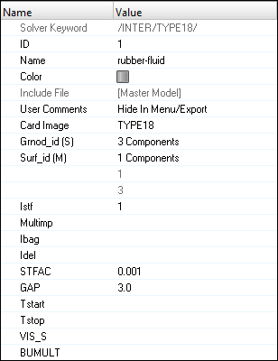
| 3. | To set the Surf_id (M), change the selector to Components and select the rubber component. |
| 4. | To set the Grnod_id (S), change the selector to Components and select all the comps, except rubber. |
Step 9: Create Boundary Conditions on outermost faces of solid comps
| 1. | Click Tools > BCs Manager. |
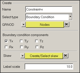
| 2. | For Name, enter constraint-X, set Select type as Boundary Condition and set the GRNOD to Nodes. |
| 3. | Click Nodes and select a node for each outer face parallel to x-axis. |
| 4. | Click Nodes in the panel and select by face. |
HyperMesh will automatically select all nodes in the face.
| 6. | Repeat Steps 9.1 to 9.5 to create Boundary conditions on Y and Z faces (see image below for reference). |
| 7. | Check the box Ty in order to constrain the translational d.o.f in Y-direction, as shown below: |
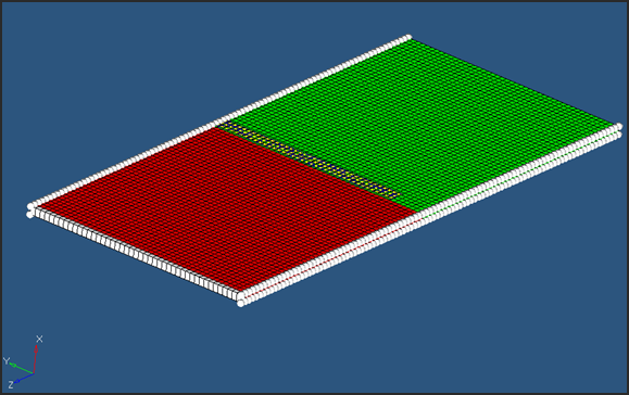
Boundary conditions for Y-axis
| 8. | Check the box next to Tz in order to constrain the translational d.o.f in Z-direction, as shown below: |
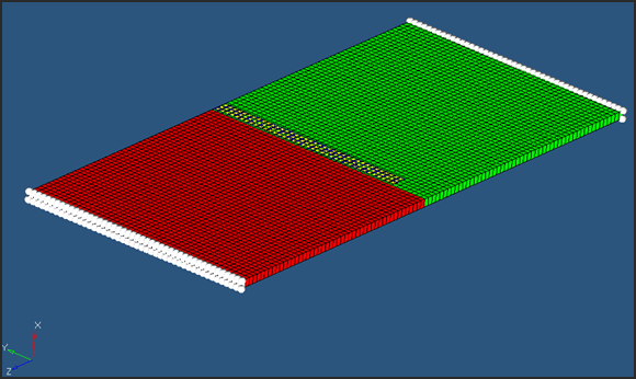
Boundary conditions for Z-axis
Step 10: Create Boundary Condition to fix one end of the rubber
| 1. | For Name, enter Fix-rubber, set Select type to Boundary Condition and set the GRNOD to Nodes. |
| 2. | Select all the nodes on the edge of the clapper, as shown below. |
| 3. | Constraint all the translational degree’s of freedom. |
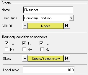
| 4. | Click Create to create the constraint. |
Step 11: Create output requests an control cards
| 1. | Launch the HyperMesh Solver browser from View > Browsers > HyperMesh > Solver. |
| 2. | Right-click in the Solver browser general area to create the cards shown below with the given values for each parameter: |
Keyword Type
|
Keyword
|
Parameter
|
Parameter Value
|
CONTROL CARDS
|
TITLE
|
Status
|
[Checked]
|
CONTROL CARDS
|
TITLE
|
TITLE
|
CLAPPER
|
CONTROL CARDS
|
MEMORY
|
Status
|
[Checked]
|
CONTROL CARDS
|
MEMORY
|
NMOTS
|
40000
|
CONTROL CARDS
|
SPMD
|
Status
|
[Checked]
|
CONTROL CARDS
|
IOFLAG
|
Status
|
[Checked]
|
CONTROL CARDS
|
ANALY
|
Status
|
[Checked]
|
ALE-CFD-SPH
|
ALE_CFD_SPH_CARD
|
Status
|
[Checked]
|
ALE-CFD-SPH
|
ALE_CFD_SPH_CARD
|
ALE_Grid_Velocity
|
[Checked]
|
ALE-CFD-SPH
|
ALE_CFD_SPH_CARD
|
GridVel_Gamma
|
100.00
|
ALE-CFD-SPH
|
ALE_CFD_SPH_CARD
|
GridVel_Cwx
|
1.00
|
ALE-CFD-SPH
|
ALE_CFD_SPH_CARD
|
GridVel_Cwy
|
1.00
|
ENGINE KEYWORDS
|
RUN
|
Status
|
[Checked]
|
ENGINE KEYWORDS
|
RUN
|
RunName
|
CLAPPER
|
ENGINE KEYWORDS
|
RUN
|
Tstop
|
50.100
|
ENGINE KEYWORDS
|
PARITH
|
Status
|
[Checked]
|
ENGINE KEYWORDS
|
PARITH
|
Keyword2
|
OFF
|
ENGINE KEYWORDS
|
PRINT
|
Status
|
[Checked]
|
ENGINE KEYWORDS
|
PRINT
|
N_Print
|
-1000
|
ENGINE KEYWORDS
|
ANIM/ELEM
|
Status
|
[Checked]
|
ENGINE KEYWORDS
|
ANIM/ELEM
|
VONM
|
[Checked]
|
ENGINE KEYWORDS
|
ANIM/ELEM
|
DENS
|
[Checked]
|
ENGINE KEYWORDS
|
ANIM/ELEM
|
PRES
|
[Checked]
|
ENGINE KEYWORDS
|
ANIM/VECT
|
Status
|
[Checked]
|
ENGINE KEYWORDS
|
ANIM/VECT
|
CONT
|
[Checked]
|
ENGINE KEYWORDS
|
ANIM/DT
|
Status
|
[Checked]
|
ENGINE KEYWORDS
|
ANIM/DT
|
Tstart
|
0
|
ENGINE KEYWORDS
|
ANIM/DT
|
Tfreq
|
0.5
|
ENGINE KEYWORDS
|
DT
|
Status
|
[Checked]
|
ENGINE KEYWORDS
|
DT
|
Tscale
|
0.5
|
ENGINE KEYWORDS
|
DT
|
Tmin
|
0.0
|
Step 12: Export the model
| 1. | Click File > Export or click the Export icon  . . |
| 2. | For File:, click the folder icon and navigate to the destination directory where you want to export to. |
| 3. | For Name, enter clapper and click Save. |
| 4. | Click the downward-pointing arrows next to Export options to expand the panel. |
| 5. | Click Merge starter and engine file to export solver deck as one file (or export separately). |
| 6. | Click on Export to export solver deck. |
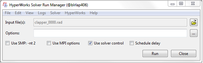
Step 13: Run the solver using RADIOSS Manager
| 1. | Launch Start > Programs > Altair HyperWorks 14.0 > RADIOSS. |
| 2. | For Input file, browse to the exercise folder and select the file clapper_0000.rad. |
See Also:
RADIOSS Tutorials


