|
»Click here to display Table of Contents«
|

Annex: Tank Test |

|

|

|

|
|
Annex: Tank Test |
|
|
|

|
|
»Click here to display Table of Contents«
|
Annex: Tank Test |
|
|
|
|
|
Annex: Tank Test |
|
|
|
|
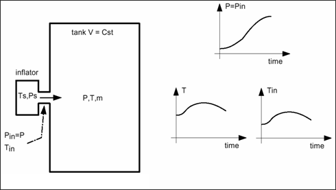
From a tank test output, it is possible to obtain the temperature and the mass flow of the gas supplied needed for the RADIOSS inputs.
With a tank test it is possible to measure the pressure at the injection point or in the middle of the tank, the two values are equal so the pressure variation is well known. Also, the amount of gas supplied and the characteristics of the gas are known.
For the temperature this is not the case, due to the fact that sometimes the temperature gauges are not accurate enough, the temperature obtained may be wrong.
The mass flow rate is not known.
The following cases take into account the fact that whether or not you know the injected temperature and the temperature in the tank.
In case the temperature at the injector and in the tank is not known:
| • | Initial and injected gas composition |
Knowing the molecular weight (MWi) of each elements and the molar fraction (Xi), it is possible to define the molar weight of the gas (MW):
![]()
The average heat capacity, per mass unit of a mixture of gases is given by the Amagat-Leduc equation:
 | (1) |
Using the previous equation, the heat capacity coefficients (Cp(T)) of the initial and injected mixture may be defined.
Knowing the characteristics of the injected gas, the initial gas, and the mixture, it is possible to find the mass flow and the temperature for the inflator. The following basic equations are used to carry out the analysis.
| • | the perfect gas equation of state is |
| • | and the adiabatic equation with H being the total enthalpy of the system (inflator + tank). |
From the conservation of the energy, the basic energy equation of the tank test can be written as:
| (4) |
Here dHout =0, due to adiabatic tank test and dV =0, due to a constant volume of the tank test.
Therefore, the equation (4) is summarized in the following equation:
| (5) |
![]()
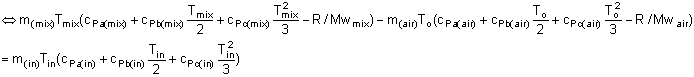
In equation (5), the unknown variable is only Tin.
The other variables are known or could be determined using the equations (1) and (2):
| • | min, mair = Mwair * PoV / (RTo), nmix = (min/Mwin) + (mair / Mwair) |
| • | for i = a to c: cpi(in), cpi(air), cpi(mix) are calculated with the equation (1), and |
| • |
Therefore, equation (5) finds the temperature at the injector Tin of the injected gas by iterating on Tin. First, the temperature is guessed and six iterations are sufficient to converge to the solution.
Knowing the evolution of the pressure versus time at the top of the tank test, it is possible to determine the mass flow rate with the following equation:
![]() (6)
(6)
With, ![]() being the total pressure variation during the experiment and
being the total pressure variation during the experiment and ![]() being the total injected mass.
being the total injected mass.
The previous equation may be written if the variation of mass versus the variation of the pressure is a function strictly growing, which is the case.
The following figure shows the evolution of the mass flow versus time.
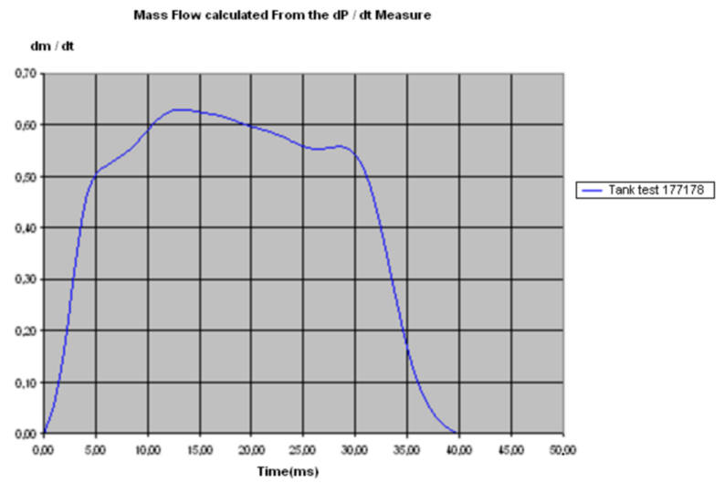
Mass flow curve
Since the pressure is quickly uniform, the following equation may be written: Pin = P(t), knowing Tin the density may be expressed as a function of Tin and P(t):
Beside  , the sound speed into the gas is equal to:
and if Vin > cin, then Vin = cin the velocity is major by the sound speed velocity.
| 1. | If the injector temperature is known: |
| 2. | If the temperature in the tank is known: |
| 3. | If the temperature in the tank is constant: |
Tin = T / ![]()