|
»Click here to display Table of Contents«
|

FVM Airbag Guidelines |

|

|

|

|
|
FVM Airbag Guidelines |
|
|
|

|
|
»Click here to display Table of Contents«
|
FVM Airbag Guidelines |
|
|
|
|
|
FVM Airbag Guidelines |
|
|
|
|
Airbag numerical models are created for numerical simulation of crash events related to occupant safety problems. Airbag models may differ in the amount of detail and accuracy depending on their intended application.
The airbag model should possess all typical features of airbag hardware: detailed representation of gas generator, housing, retainers, interchamber components, vent holes, coated fabric definition, fabric porosity for non-coated fabric, stripes, tethers, seams, etc.
The geometry, mass, inertia properties, and materials of the airbag model should correspond to hardware and CAD data.
The set of airbag components, external surfaces, internal surfaces, and vents, should be arranged in separate /SUBSET s.
Each airbag model should represent a model to be run independently and used in other component or full vehicle models as include files.
Airbag model shall be provided in design position. The airbag positioning inside a component model or full car model should be performed through the use of /TRANSFORM cards.
Airbag fabric should be meshed in non-folded state with tria elements with maximum element side of 5mm, with an average element size of 4mm. Greater size is acceptable only for vent holes and other components with void material (inter-chamber void). All nodes of these components should be attached to surrounding fabric components.
External airbag fabric components should form a closed volume with normals directed outwards. Intersections between any airbag components (external, internal, inflator, or housing) are not allowed.
The airbag fabric has a low modulus of elasticity and therefore normally small elements size does not affect time step.
Airbag folding should be performed using pre-simulation according to the CAD folding plan. The folding model should use validated fabric material definitions and contacts. RADIOSS is the preferred solver for pre-simulation folding. This guaranties that the folded model will work correctly with the airbag internal contact definition listed in corresponding sections.
Reference geometry should be represented as flat node based (/XREF) or element based (/EREF) geometry. In the case of element based geometry, the reference geometry can be disjointed.
In some cases, /XREF can also be used to represent disjointed reference geometry. In this case, each component referred to in the card should be uni-connected
The reference geometry should be parallel to global XY plane.
For closed airbag reference geometry based on nodes, /XREF:
| • | geometrical center of non-folded airbag should be at point X=0, Y=0, or Z=0 |
| • | normal directions of components in reference geometry should be the same as in folded airbag model |
| • | intersections are not allowed in non-folded airbag reference geometry |
For disjointed airbag reference geometry based on elements, /EREF:
| • | each components should be in Z=0 plane |
| • | normal directions of components in reference geometry should be the same as in folded airbag model |
In some cases during design iterations, reference geometry can be modified or morphed in order to investigate influence of minor airbag shape variations to airbag characteristics.
| Note: | With given reference geometry, the time step for fabric component is calculated based on elements size of the reference geometry. |
The gas generator model should represent all details available in CAD data: gas generator, injector openings, and retainers. The injector opening represents a collection of elements (each in a separate components) on inflator surface. Inflator components are modeled as shells with LAW2 material and /RDBODY rigid body spider. Mass and inertia properties of inflator components should correspond to hardware.
Inflator and injector elements
Injection direction is opposite to the normal direction of element. Elements from different injectors should not share common nodes. Elements from a vent hole should not share common nodes with injector elements.
Injector surface can also be defined on an internal surface, in which case the gas flow direction is opposite to the internal surface normal orientation.
The inflator definition represents the real composition of the gas. Each injected gas should be specified as a separate material card /MAT/GAS/MASS.
#---1----|----2----|----3----|----4----|----5----|----6----|----7----|----8----|----9----|---10----|
/MAT/GAS/MASS/1
Gas A
# MW
.032
# Cpa Cpb Cpc Cpd Cpe
800.001 0.3 -1.001E-4 0 0
# Cpf
0
#---1----|----2----|----3----|----4----|----5----|----6----|----7----|----8----|----9----|---10----|
Example of injected gas component
Input is the molecular weight and coefficients of specific heat coefficient for each of injected gas components.
![]()
Function CP(T) should be monotonically increasing for temperatures between ambient temperature and maximum temperature value given in temperature curves of injector.
Composition of the injected gas, injection mass flow and temperature for each gas components are determined in /PROP/INJECT1.
#---1----|----2----|----3----|----4----|----5----|----6----|----7----|----8----|----9----|---10----|
/PROP/INJECT1/1
Inflator 1
# Ngases Iflow Ascale_T
5 1 1
# mat_ID fct_IDM fct_IDT Fscale_M Fscale_T
1 2 1 0 0
# mat_ID fct_IDM fct_IDT Fscale_M Fscale_T
2 3 1 0 0
# mat_ID fct_IDM fct_IDT Fscale_M Fscale_T
3 4 1 0 0
# mat_ID fct_IDM fct_IDT Fscale_M Fscale_T
4 5 1 0 0
# mat_ID fct_IDM fct_IDT Fscale_M Fscale_T
5 6 1 0 0
#---1----|----2----|----3----|----4----|----5----|----6----|----7----|----8----|----9----|---10----|
Example of injector definition
This card is referenced in /MONVOL/FVMBAG1 card.
Injector Time to Fire (TTF) should be determined through sensor in /MONVOL/FVMBAG1, not through a shift of mass and temperature curves.
When the inflator is determined correctly and referenced in /MONVOL/FVMBAG1, RADIOSS Starter outputs the list of elements used as injector surface.
ELEM: 92 <-> SH3N : 55261587 - INFLATOR : 1
ELEM: 502 <-> SH3N : 55262048 - INFLATOR : 1
ELEM: 622 <-> SH3N : 55261581 - INFLATOR : 1
ELEM: 627 <-> SH3N : 55261568 - INFLATOR : 1
ELEM: 633 <-> SH3N : 55262068 - INFLATOR : 1
ELEM: 814 <-> SH3N : 55261601 - INFLATOR : 1
The inflator model should be validated through tank test simulation. The tank test report includes pressure and temperature measured in the test, injector mass flow, and temperature curves for each of gas component and correspondence between calculated average pressure and temperature and tank test curves.
Material for the air inside of the airbag should be specified either through /MAT/GAS/MASS, or using predefined air definition /GAS/MAT/PREDEF.
#---1----|----2----|----3----|----4----|----5----|----6----|----7----|----8----|----9----|---10----|
/MAT/GAS/MASS/50000002
initial_1
# MW
# .028008714
2.800871396197E-02
# Cpa Cpb Cpc Cpd Cpe
953.129 .229151 -2.04791E-5 0 0
# Cpf
0
#---1----|----2----|----3----|----4----|----5----|----6----|----7----|----8----|----9----|---10----|
Generic material card for air (kg, mm, ms)
This material is referenced in /MONVOL/FVMBAG1. Initial air should be used in tank test simulation.
Airbag material should be linear orthotropic material (LAW19) or non-linear anisotropic material (LAW58).
Material should be tested and validated with Picture Frame Test, Biaxial Tension Test and Uniaxial Tension Test in weft and wrap directions.
A picture frame test determines G12 shear modulus for LAW19 and dependence of G12 based on anisotropy angle for LAW58.
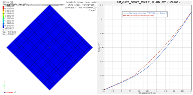
Picture frame simulation and G12(alpha) curve
Biaxial test determines material LAW19 and LAW58 stiffness in weft and wrap directions.
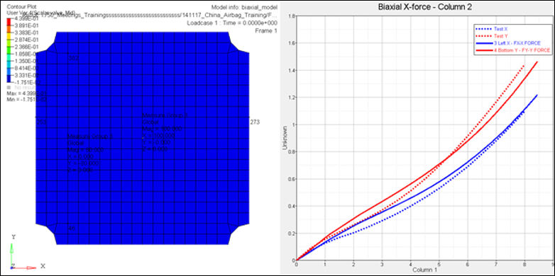
Biaxial simulation and forces displacement curves in warp and weft directions
Uniaxial test determines initial fabric stiffness for LAW58.
Airbag stripes and tethers are normally loaded uniaxially only. A uniaxial tension test should be completed and validated for these materials. Validation of 45 degree oriented probe is important.
At present time LAW19 and LAW58 materials cannot represent hysteresis effect in cyclic loading. This effect will be ignored in material definition and validation.
#---1----|----2----|----3----|----4----|----5----|----6----|----7----|----8----|----9----|---10----|
/MAT/LAW19/1
Fabric
# RHO_I
8E-7
# E11 E22 NU12
.38 .38 .35
# G12 G23 G31
.14 .14 .14
# R_E ZEROSTRESS sens_ID
.01 1 1
#---1----|----2----|----3----|----4----|----5----|----6----|----7----|----8----|----9----|---10----|
/MAT/LAW58/2
Fabric
# RHO_I
8E-7
# E1 B1 E2 B2 FLEX
0.380 0 0.380 0 0
# G0 GT AlphaT0 Gsh sens_ID
0.140 0.140 10 0 1
# Df Ds Gfrot ZEROSTRESS
0 0 0 1
# N1 N2 S1 S2
1 1 0 0
#---1----|----2----|----3----|----4----|----5----|----6----|----7----|----8----|----9----|---10----|
Generic LAW19 and LAW58 materials in kg, mm, ms
Stiffness reduction parameter R_E in material LAW19 should be set to a rather small value (normally 0.01 is enough) to remove stresses in compression. In LAW58, stiffness reduction in compression is controlled by the parameter, FLEX. This parameter is validated in a uniaxial tension test and should be set to a small value.
The material parameter ZEROSTRESS should be set to 1 and a sensor should be used in the material for activation of reference geometry. This should be the same sensor which is used to start the first injector in /MONVOL/FVMBAG1.
Property /PROP/TYPE9 (SH_ORTH) should be used with LAW19:
#---1----|----2----|----3----|----4----|----5----|----6----|----7----|----8----|----9----|---10----|
/PROP/SH_ORTH/1
Bag-3 Haut
# Ishell Ismstr
4 1
# hm hf hr dm dn
0 0 0 0 0
# N Istrain Thick Ashear Ithick Iplas
1 0 .3 0 0 0
# Vx Vy Vz Phi
0 1 0 0
#---1----|----2----|----3----|----4----|----5----|----6----|----7----|----8----|----9----|---10----|
Generic /PROP card to be used with LAW19, kg, mm, ms
Membrane formulation (no bending stiffness) is provided when N=1.
Ishell=4 and Ismstr=1 should be used for airbags with only tria elements. When reference geometry is applied, this activates a special “total small stain” formulation developed specifically for airbag simulations.
Property /PROP/TYPE16 (SH_FABR) should be used with LAW58:
#---1----|----2----|----3----|----4----|----5----|----6----|----7----|----8----|----9----|---10----|
/PROP/TYPE16/1
Shell
# Ishell Ismstr Ish3n
4 4 0
# hm hf hr dm dn
0 0 0 0 0
# N Istrain Thick Ashear Ithick Iplas
1 0 0.3 0 0 0
# Vx Vy Vz Isk Ipos
1 0 0 0 0
# Phi Alpha Thick Z Mat
0 0 0.3 0 1
#---1----|----2----|----3----|----4----|----5----|----6----|----7----|----8----|----9----|---10----|
Generic /PROP card to be used with LAW58, kg, mm, ms
Only membrane formulation (no bending stiffness) is available for this property N=1.
Ishell=4 and Ismstr=4 should be used for airbags with only tria elements.
/PROP/TYPE16 (SH_FABR) refers to the fabric material inside of the card. This should be exactly the same material used in the /PART card definition.
Material directions are determined by specifying global Vx, Vy, and Vz vectors which are projected on each element of the reference geometry of airbag and then rotated by the angle of Phi. This gives the first material direction. The second material direction is perpendicular to it for LAW19 or it is a given angle Alpha (default 90 degrees) for LAW58.
| Note: | Default parameters of hourglass and damping coefficients hm, hf, hr, dm, and dn work well when the quality of the airbag folding is good. |
In RADIOSS the standard method for airbag calculation is Finite Volume Method (FVM). FVM models gas flow inside the airbag, including the interaction with internal airbag components (internal walls, baffles, stripes, etc.). The airbag card, /FVMBAG1 is used to activate the FVM airbag method. Uniform pressure airbags can be used only for debugging purposes, such as checking unfolding, contacts, and global consistency of gas dynamic parameters. /AIRBAG1 can be used to activate a uniform pressure airbag for debugging.
#---1----|----2----|----3----|----4----|----5----|----6----|----7----|----8----|----9----|---10----|
/MONVOL/FVMBAG1/1
SAB
# Isur
4
# Ascale_T Ascale_P Ascale_S Ascale_A Ascale_D
0 0 0 0 0
# mat_ID Pext T_0 Iequi Ittf
5000 1.0135E-4 296 3
# Njet
1
#inject_ID sens_IDsurf_IDinj
10001 22 19
#fct_IDvel Fscale_vel
4 0
# Nvent
0
# Iframe
0
# l1 l2 l3
# Nb1 Nb2 Nb3 grbric_ID surf_IDin Iref
0 0 0 21 20 0
# Igmerg Cgmerg Cnmerg Ptole
1 1e-04 1e-04 0
# qa qb Hmin
0
# Ilvout Nlayer Nfacmax Nppmax ifvani
0 0 0 0 1
/SURF/PART/4
AIRBAG EXTERNAL SURFACE
1 2 4 5 6 7
/SURF/PART/19
INJECTOR SURFACE
5
/SURF/PART/20
INJECTOR SURFACE
5
/GRBRIC/PART/21
TETRA4
8
#---1----|----2----|----3----|----4----|----5----|----6----|----7----|----8----|----9----|---10----|
Generic /FVMBAG1 card
Closed airbag external surface should be defined using /SURF/PART, referring to a set of shell components with normals directed outwards.
Scaling parameters, Ascale_T, Ascale_P, Ascale_S, Ascale_A, and Ascale_D are not used.
Atmospheric values are defined for initial air material, initial temperature, and initial pressure.
The parameter, Ittf should be set to 3. In this case, vents are activated at TTF of the first injector given in the sensor referenced in /MONVOL/FVMBAG1 and all time dependent curves controlling vent openings will be shifted by the time of activation of first injector, plus time given in Tstart. In the card above it, the parameter Ittf is not active, because there are no vent holes specified.
The number of injectors should refer to the /PROP/INJ1 card. Elements used as injection surface should be collected in a separate component, which belongs either to external or internal airbag surface.
Time to fire (TTF) to start gas injection should be defined in /SENSOR. Global parameter definition /PARAMETER can be used to parametrize input of the TTF and other airbag parameters.
The function for injection velocity should be set at a constant value of approximately the velocity of sound of injected gas. This function does not have significant impact to simulation results.
Internal surfaces (internal walls, baffles, bands, etc.) shall be defined as a collection of components and referenced in the surf_IDin field. It is also recommended to represent inter-chamber openings as separate void components with all nodes attached to fabric component. That will avoid merging of finite volumes which belongs to different chambers of airbag during deployment simulation.
External and internal airbag components, including inter-chamber voids and void components used to represent venting should not have geometrical intersections. The creation of the finite volume mesh is not possible when any intersection is available.
Internal fabric components shall be modeled with similar materials and properties as external fabric components. Internal components of injector system shall be modeled as rigid shells with LAW2 and rigid spider in /RBODY.
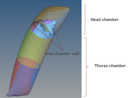
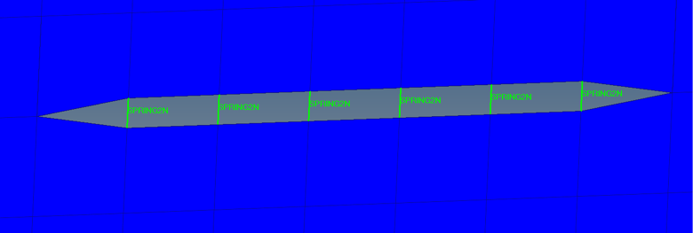
Simple sleeve airbag with 2 chambers
Initial finite volume mesh can be created in HyperMesh or SimLab. All external and internal components of the airbag should be accounted for the creation of the mesh.
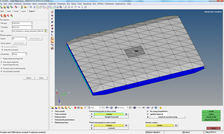
HyperMesh window to create initial finite volume tetra mesh. 1568 tetras created
The finite volume mesh should be a separate component of 4 node tetra elements which completely fill the airbag volume.
#---1----|----2----|----3----|----4----|----5----|----6----|----7----|----8----|----9----|---10----|
/PART/8
TETRA4
8 8 0
/MAT/VOID/8
tetra
/PROP/VOID/8
tetra
#---1----|----2----|----3----|----4----|----5----|----6----|----7----|----8----|----9----|---10----|
Example of tetra component definition of initial Finite Volume mesh inside of airbag
To make sure that the tetra mesh is filling the internal airbag volume completely, verify that the airbag volume output in the Starter .out file is the same finite volume listed in the same file. Also, verify that the number of finite volumes (1568 in present case) is the same as the number of tetras created in Simlab or HyperMesh.
INITIAL VOLUME OF MONITORED VOLUME. . .= 299199.9998912
VOLUME NUMBER 1
NUMBER OF SURFACE POLYGONS. . . . . . .= 1200
NUMBER OF SURFACE TRIANGLES . . . . . .= 1200
NUMBER OF COMMUNICATION POLYGONS. . . .= 2536
NUMBER OF COMMUNICATION TRIANGLES . . .= 2536
NUMBER OF FINITE VOLUMES. . . . . . . .= 1568
MIN FINITE VOLUME VOLUME. . . . . . . .= 66.66666700000 (FINITE VOLUME ID 292)
INITIAL MERGING VOLUME. . . . . . . . .= 19.08163264612
SUM VOLUME OF FINITE VOLUMES. . . . . .= 299199.9998912
SUM AREA SURFACE TRIANGLES. . . . . . .= 230031.1439046
SUM MASS OF FINITE VOLUMES. . . . . . .= 3.9428379122204E-04
Another way to verify that tetra mesh fills the airbag volume completely is to search for the following warning messages:
WARNING ID : 631
** WARNING IN FVMBAG DEFINITION
DESCRIPTION :
-- MONITORED VOLUME ID : 1
-- MONITORED VOLUME TITLE : SAB
IN LOCAL FRAME DIRECTION 1
GIVEN LENGTH 0.000000000000 IS SMALLER THAN BOUNDING LENGTH 301.4996942325
IT IS RESET TO 304.5146911748
WARNING ID : 631
** WARNING IN FVMBAG DEFINITION
DESCRIPTION :
-- MONITORED VOLUME ID : 1
-- MONITORED VOLUME TITLE : SAB
IN LOCAL FRAME DIRECTION 2
GIVEN LENGTH 0.000000000000 IS SMALLER THAN BOUNDING LENGTH 100.0000000000
IT IS RESET TO 101.0000000000
WARNING ID : 631
** WARNING IN FVMBAG DEFINITION
DESCRIPTION :
-- MONITORED VOLUME ID : 1
-- MONITORED VOLUME TITLE : SAB
IN LOCAL FRAME DIRECTION 3
GIVEN LENGTH 0.000000000000 IS SMALLER THAN BOUNDING LENGTH 1.535460483274
IT IS RESET TO 1.550815088107
These messages indicate that RADIOSS has found an empty space inside of the airbag volume and is trying to fill it automatically. The message should not appear when the initial volume is defined using a manually created tetra mesh in HyperMesh or SimLab.
The quality of tetra mesh is not important because finite volumes based on the tetra mesh will be merged according to strategy provided by merging parameters. The parameters Igmerg, Cgmerg, and Cnmerg are available in /FVMBAG1. However, it is recommended to deactivate the merging process during Starter initialization by setting Cgmerg = Cnmerg=1e-04 and use an advanced merging algorithm in the Engine, where the same parameters can be activated in /FVMBAG/MODIF or /DT/FVMBAG.
The parameter Ifvani should be set to 1. RADIOSS creates an animation file *A000 which represents initial finite volumes.
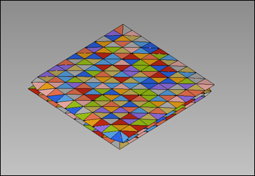
Representation of initial finite volumes in *A000 file
The number of tetra elements depends on complexity and the type of airbag. For example, a side head thorax airbag can be about 30.000 to 50.000 tetras, for other airbags 100.000 to 150.000 tetras.
During the simulation, RADIOSS will merge finite volumes according to global and neighbor relative size and finite element time step. Therefore, the number of finite volumes is reduced rather quickly. However, it is important to have a smooth reduction of number of finite volumes and a sufficient number of finite volumes at the end of simulation (1% - 10% of the initial number).
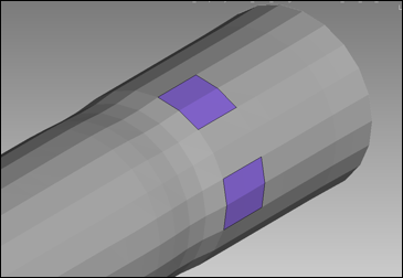
Each vent hole should be represented as a separate component in the same position as in the CAD data. To model physical hole, the component can be modeled with void material and property (not mandatory). All nodes of the void vent components should be connected to a fabric component. Density, Young’s modulus and thickness should be defined for the void components. These values should correspond to the fabric material of the airbag. These values are important for the contact defined between void components which helps to maintain the internal airbag volumes.
#---1----|----2----|----3----|----4----|----5----|----6----|----7----|----8----|----9----|---10----|
/MAT/VOID/2
Material void
# RHO E
8E-7 0.38
#---1----|----2----|----3----|----4----|----5----|----6----|----7----|----8----|----9----|---10----|
/PROP/VOID/2
Property void
# Thick
0.3
#---1----|----2----|----3----|----4----|----5----|----6----|----7----|----8----|----9----|---10----|
Material and property for vent void component
Also, it is necessary to place a fabric non-vent component between the vent hole and the rest of the airbag fabric to avoid a situation where two vent components are sharing the same nodes. In the latter case, the element will be accounted only in the vent hole which is determined later.
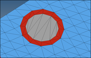
Blue- airbag fabric, grey- vent hole, red – component which separates vent hole from rest of airbag
/MONVOL/FVMBAG1
……….
# Sid_vent Ivent Avent Bvent
666000015 1 1 0
# Tstart Tstop dPdef dtPdef Idtpdef
0 0 1E30 0 0
# fct_IDt fct_IDP fct_IDA Fscalet FscaleP FscaleA
0 1 0 0 0 0
# fct_IDt' fct_IDP' fct_IDA' Fscalet' FscaleP' FscaleA'
0 0 0 0 0 0
………
/FUNCT/1
1 vent activation function
# X Y
-1 0
0 0
1e-06 0
2e-06 1
1 1
Definition of isenthalpic vent hole and threshold function to activate the vent hole (kg, mm, ms)
The vent hole should be activated after an overpressure is reached near the finite volumes facing the vent hole. It is advised to use 1e-06GPa (1% atmospheric pressure). Note that in version 14.0 the activation of vent hole can be performed directly by the value of dPdef. The curve specification is not necessary anymore.
The Starter outputs a list of elements which belong to each vent hole.
ELEM: 46991 <-> SH3N : 55089506 - VENT HOLE: 1
ELEM: 46992 <-> SH3N : 55089507 - VENT HOLE: 1
ELEM: 46993 <-> SH3N : 55089508 - VENT HOLE: 1
ELEM: 46994 <-> SH3N : 55089509 - VENT HOLE: 1
ELEM: 46995 <-> SH3N : 55089510 - VENT HOLE: 1
ELEM: 46996 <-> SH3N : 55089511 - VENT HOLE: 1
ELEM: 46997 <-> SH3N : 55089512 - VENT HOLE: 1
To simplify variation of the vent hole diameter, several circular components can be used to fill the vent hole area. Adding more components with a greater diameter to vent hole definition enables the consideration of vent holes with greater area. In this case all the vent hole components should be the same as the neighboring fabric component.
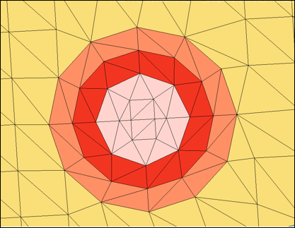
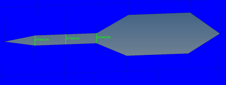
Vent hole with variable diameter
The edges of the slit vent should be connected with stiff springs /PROP/TYPE4 to provide proper folding of the airbag in the area near the slit vent. The springs can also be used to vary the length of the slit vent. Closed edges of the vent should be modeled using stiff springs to avoid opening.
Slit vent modeling
Porosity of airbag material is modeled as a regular vent hole type Iform=2. This type of vent hole requires an additional porosity function of volumetric outflow versus overpressure inside of the airbag (Chemkin curve fct_IDV). RADIOSS applies the gas pressure to the airbag vent component with scaling coefficient of (1-Avent). To model fabric porosity and have non-zero pressure applied to the vent, the component area should be scaled down by a small value of Avent (Avent=0.01) and then the ordinate of the Chemkin curve defined by fct_IDV should be scaled up by the factor of 1/Avent, to keep the same mass flow out.
Similar to vent holes, the porous components should be separated from each other and from other vent holes by at least one row of elements.
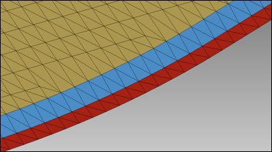
Porous fabric (yellow) is separated from permeable seam (red) by blue non-vent component
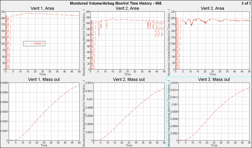
It is recommended to output the following to the time history file:
| • | Global gas dynamic parameters: mass of gas, volume of airbag, area of airbag, pressure (average), temperature (average), and heat capacity coefficients (average) |
| • | For each vent hole: vent area, outflow velocity, and outflow mass |
| • | Finite volume parameters: number of finite volumes and smallest finite volume time step |
#---1----|----2----|----3----|----4----|----5----|----6----|----7----|----8----|----9----|---10----|
/TH/MONV/666000001
Airbag MonVol Time History - 666
# var1 var2 var3 var4 var5 var6 var7 var8 var9 var10
DEF GAS OUT1 OUT2 OUT3 OUT4 OUT5 NFV DTBAG
# Obj1 Obj2 Obj3 Obj4 Obj5 Obj6 Obj7 Obj8 Obj9 Obj10
666000001
#---1----|----2----|----3----|----4----|----5----|----6----|----7----|----8----|----9----|---10----|
Generic time history output card with 5 vent holes
Local pressure should also be output at the location where it was measured in test (near injector).
#---1----|----2----|----3----|----4----|----5----|----6----|----7----|----8----|----9----|---10----|
/GAUGE/1
FWD
# node_ID shell_ID DIST
50050421
#---1----|----2----|----3----|----4----|----5----|----6----|----7----|----8----|----9----|---10----|
/TH/GAUGE/1
TH GAUGE
# var1 var2 var3 var4 var5 var6 var7 var8 var9 var10
DEF
# Obj1 Obj2 Obj3 Obj4 Obj5 Obj6 Obj7 Obj8 Obj9 Obj10
1
#---1----|----2----|----3----|----4----|----5----|----6----|----7----|----8----|----9----|---10----|
Generic time history output card for pressure gauge
The following cards should be used in the Engine file for animation requests output gas pressure, density, temperature, and fluid velocities in airbag surface nodes:
Use HyperCrash's penetration checker to check external and internal airbag components including inter-chamber voids and void components used for vents should not have geometrical intersections.
Use a combination of /INTER/TYPE7 and /INTER/TYPE11 contacts to represent internal airbag contact.
#---1----|----2----|----3----|----4----|----5----|----6----|----7----|----8----|----9----|---10----|
/INTER/TYPE7/666700001
Airbag Selfcontact - 666700001
# grnd_IDs surf_IDm Istf Ithe Igap Ibag Idel Icurv Iadm
666100103 666100101 4 0 0 1 0 0 0
# Fscale_gap GAP_MAX Fpenmax
0 0 0
# STMIN STMAX %MESH_SIZE dtmin
1 1E30 0 0
# STFAC FRIC GAP_MIN Tstart Tstop
1 0 1 0 0
# I_BC INACTI VIS_S VIS_F BUMULT
000 6 0 0 0
# Ifric Ifiltr Xfreq Iform
0 0 0 2
/SURF/PART/666100101
Airbag External Surface by Part - 666100101
666000001 666000002 666000003 666000004 666000005 666000006 666000007 666000008 666000009 666000013
666000014 666000015 666000016 666000017 666000018 666000201 666000202 666000203
#---1----|----2----|----3----|----4----|----5----|----6----|----7----|----8----|----9----|---10----|
Generic /INTER/TYPE7 airbag contact (kg, mm, ms)
For /INTER/TYPE7 contact:
| • | All external and internal fabric components including inter-chamber voids and void components for vents should be listed both on slave and master side |
| • | Istf=4 provides correct contact stiffness |
| • | Ibag=1 provides vent closure due to contact |
| • | STMIN=1KN/mm limits smallest contact stiffness |
| • | GAP_MIN=1mm provides a smooth increase of contact force as slave nodes are approaching master segment |
| • | Friction is set to 0 |
| • | INACTI=6 deactivates initial penetrations |
Initial penetration can be checked with HyperCrash’s penetrations checker. The airbag model should be depenetrated up to the physical thickness of airbag fabric. For example, if the thickness of airbag fabric is 0.3mm, the airbag should be depenetrated to 30% of GAP_MIN = 1 value.
#---1----|----2----|----3----|----4----|----5----|----6----|----7----|----8----|----9----|---10----|
/INTER/TYPE11/666800001
Airbag Selfcontact Edge - 666800001
# line_IDs line_IDm I_stf I_gap Multimp Idel
666100102 666100102 4 0 0 0
# STMIN STMAX MESH_SIZE dtmin Iform sens_ID
1 0 0 0 2 0
# STFAC FRIC GAPmin Tstart Tstop
1 0 0.9 0 0
# I_BC INACTI VIS_S VIS_F BUMULT
000 6 0 0 0
/LINE/SURF/666100102
Airbag Line by Surface - 666100102
666100101
#---1----|----2----|----3----|----4----|----5----|----6----|----7----|----8----|----9----|---10----|
Generic /INTER/TYPE11 airbag contact (kg, mm, ms)
For /INTER/TYPE11 contact:
| • | All external and internal fabric components including inter-chamber voids and void components for vents should be listed both on slave and master side |
| • | Istf=4 provides correct contact stiffness |
| • | STMIN=1KN/mm limits smallest contact stiffness |
| • | GAP_MIN=0.9mm provides a smooth increase of contact force as slave nodes are approaching master segment. This contact gap is 90% of /INTER/TYPE7 contact gap |
| • | Friction is set to 0 |
| • | INACTI=6 deactivates initial penetrations |
Initial penetration can be checked with HyperCrash’s penetrations checker. The airbag model should be depenetrated tol 90% of GAP_MIN value.
Assuming there are no initial intersections in the model, the definition of a TYPE7 and TYPE11 contact prevents node-to-surface and edge-to-edge intersections during airbag simulation. If initial intersections exist in the model, the model can be unstable, due to a hung nodes at the intersection which can cause a time step reduction. In addition to this, as mentioned in “Finite volume method airbags”, the finite volume mesh cannot be created when airbag components have intersections. Therefore, it is important to remove all initial intersections.
Model time step should not be limited by the contact kinematic time step.
A folded airbag model with correct material, property, contact definition, and specified reference geometry should not move before activation of injector. To confirm this, a stability run should be done to 50ms with TTF=50ms set in the airbags sensor referenced in /MONVOL/FVMBAG1.
Applications of additional damping /DAMP, contact activation time, rigidizing of the airbag model is not allowed to prevent airbag motion before TTF.
The airbag model should not show any significant increase of stresses, strains, and non-physical motion before TTF, due to contact and reference geometry application.
Airbag housing inflator components should be accounted for the stability run with contact definition between airbag and these external components.
A uniform pressure run should be performed and documented to make sure that gas dynamic data, injector input, fabric materials, and contacts give physical results, model runs without errors, and there are no hung nodes.
To create a uniform pressure test:
| • | replace /FVMBAG1 with /AIRBAG1 keyword |
| • | remove injector surface from injector definition |
| • | comment off injector velocity curve input |
| • | keep all vents as in finite volume airbag |
| • | comment out information lines with input for finite volume bag meshing |
#---1----|----2----|----3----|----4----|----5----|----6----|----7----|----8----|----9----|---10----|
/MONVOL/AIRBAG1/1
SAB
#surf_IDex
4
# Ascale_T Ascale_P Ascale_S Ascale_A Ascale_D
0 0 0 0 0
# Mat_ID Pext T_0 Iequi Ittf
5000 1.0135E-4 296
# Njet
1
#inject_ID sens_IDsurf_IDinj
# 10001 22 19
10001 22
##fct_IDvel Fscalevel
# 4 0
# Nvent
0
## Iframe
# 0
## l1 l2 l3
#
## Nb1 Nb2 Nb3grbric_ID surf_IDin Iref
# 0 0 0 21 20 0
## Igmerg Cgmerg Cnmerg Ptole
# 1 1e-04 1e-04 0
## qa qb Hmin
# 0
## Ilvout Nlayer Nfacmax Nppmax ifvani
# 0 0 0 0 1
/SURF/PART/4
AIRBAG EXTERNAL SURFACE
1 2 4 5 6 7
#---1----|----2----|----3----|----4----|----5----|----6----|----7----|----8----|----9----|---10----|
Generic /AIRBAG1 card. Corrections are shown in red
Results of simulations should be inspected visually to control physical reliability of airbag deployment, absence of stuck or hanging nodes, time step development, energy balance, and energy error.
The airbag parameters, mass, volume, pressure, and temperature should be plotted and compared with the given airbag volume and mass of injected gas.
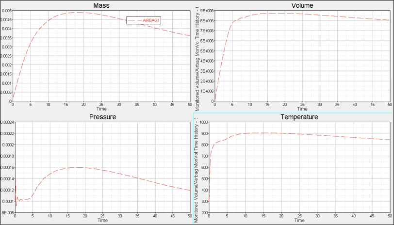
Airbag parameters to control for /AIRBAG1 run
For each vent, the vent area and vent outflow should be plotted and controlled that it corresponds to the physical sizes of the vent hole.
This data should be used later as basic for comparison to average gas dynamic data from run with /FVMBAG1 card.
FVM airbag should be run standalone. The objective of this run is to choose correct strategy for merging of finite volumes, control deployment behavior, and general airbag characteristics.
Finite volume parameters are determined in Engine file as:
/DT/FVMBAG
0.2 5.0e-05
/FVMBAG/MODIF
666000001
1 0.050 1.E-10 1
| Note: | The choice of proper merging parameters can be different from one airbag to another. Several runs can be necessary to find a good merging strategy. |
Finite volumes are merged when finite volume time step becomes less than a given value (/DT/FVMBAG) or when the size of finite volume becomes less than the average global or local finite volume size. These parameters should be tuned to provide smooth merging behavior and sufficient number of finite volumes during the complete simulation.
The number of finite volumes and finite volume time step can be controlled in HyperGraph:
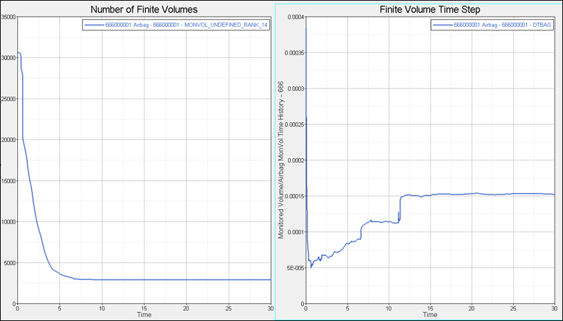
The number of finite volume should fall smoothly to 2% to 10% of initial number of finite elements. The merging strategy should also provide a time step higher than the minimal time step required in crash simulations.
The development of finite volume merging should also be checked in merging output file.
In the Engine output file:
2 0.6688E-03 0.2863E-03 FVBAG 666000001 0.0% 2.739 0.1415E-14 0.000 -0.8103E-19 0.000
** MONITORED VOLUME ID: ********TIME STEP: 0.2878E-03 FINITE VOLUME: 21940
** MONITORED VOLUME ID: ******** - FINITE VOLUME MESH UPDATE **
NUMBER OF FINITE VOLUMES : 30605
SUM VOLUME FINITE VOLUMES : 155386.459 (VOLUME AIRBA 155386.459 )
SUM AREA SURFACE POLYGONS : 227440.887 (AREA AIRBAG 227440.887 )
A reasonable number of finite volume are needed and finite volume merging should not cause the number to drop immediately to one finite volume.
For example, the finite volume time step in the /DT/FVMBAG card should be smaller than the initial finite volume time step output in the Engine output. Merging parameters in /FVMBAG/MODIF should not be very high to provide smooth finite volume merging history. It should be avoided that most of finite volume will be merged immediately to 1 finite volume.
The sum of finite volume volumes should be equal to the actual airbag volume as:
** MONITORED VOLUME ID: 1 - FINITE VOLUME MESH UPDATE **
NUMBER OF FINITE VOLUMES : 1565
SUM VOLUME FINITE VOLUMES : 298121.912 (VOLUME AIRBA 298121.912 )
SUM AREA SURFACE POLYGONS : 230093.158 (AREA AIRBAG 230093.158 )
44 0.1320 0.2865E-02 FVBAG 1 1.0% 7.222 0.1104 0.000 0.4265E-01 0.000
** MONVOL ID 1 FINITE VOLUME MESH UPDATE - LOOPING - NUMBER OF FINITE VOLUMES : 1564
** MONVOL ID 1 FINITE VOLUME MESH UPDATE - LOOPING - NUMBER OF FINITE VOLUMES : 1563
** MONITORED VOLUME ID: 1TIME STEP: 0.4293E-02 FINITE VOLUME: 396
Each time finite volumes are merged, the above message appears in the Engine output.
Animation results should be visually controlled. A temperature or velocity contour plot can be used to display the gas motion inside of airbag. The motion should clearly develop from the inflator into the airbag volume and account for the airbag topology (internal walls, baffles, vent holes, etc.).
Airbag gas parameters should be compared to uniform pressure airbag run. Significant differences should be inspected and explained.
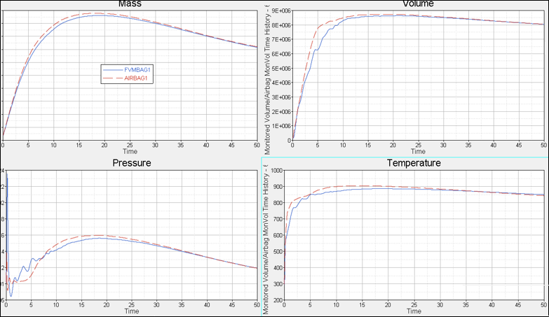
Airbag parameters for /AIRBAG1 mad /FVMBAG1 runs
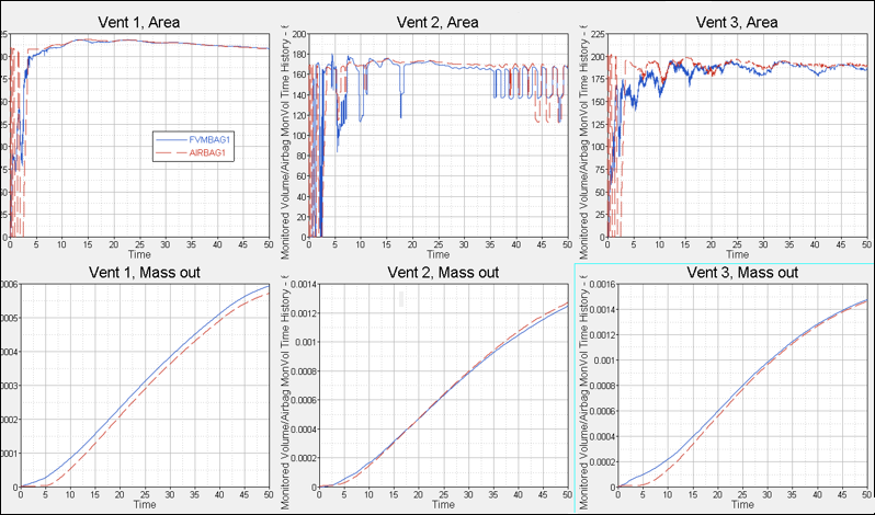
Venting parameters for /AIRBAG1 mad /FVMBAG1 runs
The vent area and vent outflow should be plotted for each vent and controlled and compared to uniform pressure run.
The airbag housing should represent all details available in CAD data.
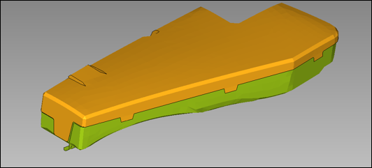
Airbag housing
The meshing requirements for the airbag components should fulfill general meshing requirement agreed with OEM. Material laws LAW2 and LAW36 are used to model elasto-plastic materials. Materials with failure should be used to reproduce the opening of an airbag cover.
Solid foam components should be modeled using LAW38 or LAW70, whereas hyperelastic components are modeling using LAW42.
Element properties for shell /PROP/TYPE1 should use Ishell=24 to avoid hourglass effects. For solid foam or hyperelastic components, use /PROP/TYPE14 with Isolid=24 and Ismstr=10.
Contact between airbag and environment should be separated into specific contacts:
| • | Airbag to inflator |
| • | Airbag to housing |
| • | Airbag to dummy |
| • | Airbag to seat structure |
#---1----|----2----|----3----|----4----|----5----|----6----|----7----|----8----|----9----|---10----|
/INTER/TYPE7/666710001
Airbag vs. Housing
# grnd_IDs surf_IDm Istf Ithe Igap Ibag Idel Icurv Iadm
666100103 666200201 4 0 0 1 2 0 0
# Fscale_GAP GAP_MAX Fpenmax
0 0 0
# STMIN STMAX %MESH_SIZE dtmin
1 1E30 0 0
# STFAC FRIC GAP_MIN Tstart Tstop
1 .1 1 0 0
# I_BC INACTI VIS_S VIS_F BUMULT
000 6 0 0 0
# Ifric Ifiltr Xfreq Iform
0 0 0 2
#---1----|----2----|----3----|----4----|----5----|----6----|----7----|----8----|----9----|---10----|
/INTER/TYPE7/666710002
Housing vs. Airbag
# grnd_IDs surf_IDm Istf Ithe Igap Ibag Idel Icurv Iadm
666100104 666200202 4 0 0 1 2 0 0
# Fscale_GAP GAP_MAX Fpenmax
0 0 0
# STMIN STMAX %MESH_SIZE dtmin
1 1E30 0 0
# STFAC FRIC GAP_MIN Tstart Tstop
1 .1 1 0 0
# I_BC INACTI VIS_S VIS_F BUMULT
000 6 0 0 0
# Ifric Ifiltr Xfreq Iform
0 0 0 2
#---1----|----2----|----3----|----4----|----5----|----6----|----7----|----8----|----9----|---10----|
/INTER/TYPE11/666810001
Airbag vs. Housing
# line_IDs line_IDm I_stf I_gap Multimp Idel
666100102 666200203 4 0 0 2
# STmin STmax MESH_SIZE dtmin Iform sens_ID
1 0 0 0 2 0
# STFAC FRIC GAP Tstart Tstop
1 0 0.9 0 0
# I_BC INACTI VIS_S VIS_F BUMULT
000 6 0 0 0
#---1----|----2----|----3----|----4----|----5----|----6----|----7----|----8----|----9----|---10----|
Generic /TYPE7 and TYPE11 contacts between airbag and housing (kg, mm, ms)
Normally two symmetric /INTER/TYPE7 contacts and one /INTER/TYPE11 edge to edge contact should be specified. Use the following contact settings for these contacts:
| • | Istf=4, provides proper contact stiffness |
| • | Ibag=1, for vent closure |
| • | Idel=2, removes deleted elements from contact |
| • | STMIN=1KN/mm |
| • | Iform=2 |
Useful checklist for airbag modeling:
| • | All components are meshed according to meshing requirements |
| • | Airbag is free from intersections |
| • | Model numeration convention is fulfilled, airbag modules are subdivided in subsets for airbag external surfaces, vents, internal surfaces housing, inflator, etc. |
| • | Airbag model is subdivided into subsets for airbag external surfaces, vents, internal surfaces housing, inflator, etc. |
| • | Mass and inertia of model corresponds to physical part |
| • | Fabric material data validated |
| • | Vent holes are modeled |
| • | Porous fabric is modeled |
| • | Gas material for each gas component is modeled |
| • | CP(T) function is increasing monotonically for each gas |
| • | Inflator is validated in tank test |
| • | Gas injections starts at TTF given in /SENSOR |
| • | Ambient and internal air material are specified |
| • | /FVMBAG1 card is specified |
| • | Internal airbag contacts specified, HyperCrash penetration check shows no intersections, maximum penetration grade is 0.9 |
| • | Stability run is done |
| • | Uniform pressure run is completed |
| • | Standalone FVM run is completed |
| • | Model runs with required time step control |
| • | Number of finite volumes does not reduce to one |
| • | Visual development of the flow (temperature contour plot, fluid velocity vector) is realistic |
The following airbag options are available in RADIOSS V14.0:
| • | Fully-integrated membrane formulation for 4 node shells on airbag surface |
| • | Anisotropic fabric material LAW58 with input of nonlinear stress strain curves for biaxial loading test in directions 1 and 2 and for picture frame test for shear. |