|
»Click here to display Table of Contents«
|

/INTER/TYPE7 |

|

|

|

|
|
/INTER/TYPE7 |
|
|

|

|
|
»Click here to display Table of Contents«
|
/INTER/TYPE7 |
|
|
|
|
|
/INTER/TYPE7 |
|
|
|
|
Block Format Keyword
/INTER/TYPE7 - Interface Type 7
Description
Interface TYPE7 is a multi-usage impact interface, modeling contact between a master surface and a group of slave nodes. It is also possible to consider heat transfer and heat friction. All limitations that were encountered with interfaces TYPE3, TYPE4 and TYPE5 are solved with this interface:
| • | A node can at the same time be a slave and a master node. |
| • | Each slave node can impact each master segment; except if it is connected to this segment. |
| • | A node can impact on more than one segment. |
| • | A node can impact on the two sides, on the edges and on the corners of each segments. |
| • | It is a fast search algorithm without limitations. |
The main limitations of this interface are:
| • | Time step is reduced in case of high impact speed or contacts with small gap; |
| • | It does not work properly if used with a rigid body at high impact speed or rigid body with small gap. |
| • | It does not solve edge to edge contact (to solve this, /INTER/TYPE11 should be used along with TYPE7). |
Format
(1) |
(2) |
(3) |
(4) |
(5) |
(6) |
(7) |
(8) |
(9) |
(10) |
/INTER/TYPE7/inter_ID/unit_ID |
|||||||||
inter_title |
|||||||||
grnd_IDs |
surf_IDm |
Istf |
Ithe |
Igap |
|
Ibag |
Idel |
Icurv |
Iadm |
Fscalegap |
Gapmax |
Fpenmax |
|
|
|
|
|||
Stmin |
Stmax |
%mesh_size |
dtmin |
Irem_gap |
Irem_i2 |
||||
Insert if Icurv = 1 or 2
(1) |
(2) |
(3) |
(4) |
(5) |
(6) |
(7) |
(8) |
(9) |
(10) |
node_ID1 |
node_ID2 |
|
|
|
|
|
|
|
|
Required Fields
(1) |
(2) |
(3) |
(4) |
(5) |
(6) |
(7) |
(8) |
(9) |
(10) |
Stfac |
Fric |
Gapmin |
Tstart |
Tstop |
|||||
IBC |
|
|
Inacti |
VISS |
VISF |
Bumult |
|||
Ifric |
Ifiltr |
Xfreq |
Iform |
sens_ID |
fct_IDF |
AscaleF |
|
||
If Ifric > 0
(1) |
(2) |
(3) |
(4) |
(5) |
(6) |
(7) |
(8) |
(9) |
(10) |
C1 |
C2 |
C3 |
C4 |
C5 |
|||||
If Ifric > 1
(1) |
(2) |
(3) |
(4) |
(5) |
(6) |
(7) |
(8) |
(9) |
(10) |
C6 |
|
|
|
|
|
|
|
|
|
If Iadm = 2
(1) |
(2) |
(3) |
(4) |
(5) |
(6) |
(7) |
(8) |
(9) |
(10) |
NRadm |
Padm |
Angladm |
|
|
|
|
|
||
If Ithe = 1
(1) |
(2) |
(3) |
(4) |
(5) |
(6) |
(7) |
(8) |
(9) |
(10) |
Kthe |
fct_IDK |
|
Tint |
Ithe_form |
AscaleK |
|
|||
Frad |
Drad |
Fheats |
Fheatm |
|
|
||||
|
|
For Istf =1000, stiffness: For Istf > 1 and Istf < 1000, stiffness:
Where, Kn is computed from both master segment stiffness Km and slave node stiffness Ks:
Where, Km is master segment stiffness and computed as follows: when the master segment lies on a shell or is shared by shell and solid:
when the master segment lies on a solid:
Where, S is the segment area; V is the volume of the solid, and B is the Bulk Modulus. Where, Ks is an equivalent nodal stiffness considered for interface TYPE7, and computed as: when the node is connected to a shell element:
when the node is connected to a solid element:
There is no limitation to the value of stiffness factor (but, a value greater than 1.0 can reduce the initial time step).
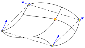
If Icurv = 2, a cylindrical curvature is defined for the gap with node_ID1 and node_ID2 (on the axis of the cylinder). If Icurv = 3, the master surface shape is obtained with a bicubic interpolation, respecting continuity of the coordinates and the normal from one segment to the other. In case of a fast and large change in curvature, this formulation might become unstable (will be improved in future version).
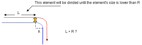
If the contact occurs in a zone (master side) whose radius of curvature is lower than the element size (slave side), the element on the slave side will be divided (if not yet at maximum level).
If the contact occurs in a zone (master side) whose radius of curvature is lower than NRadm times the element size (slave side), the element on the slave side will be divided (if not yet at maximum level). If the contact occurs in a zone (master side) where the angles between the normals are greater than Angladm and the percentage of penetration is greater than Padm, the element on the slave side will be divided (if not yet at maximum level).
If all of the master segments are brick, Gapmin is defined by:
If Igap =1, variable gap is computed as:
If Igap =2, variable gap is computed as: If Igap =3, variable gap is computed as:
Where,
gm = gm = 0 for brick elements
gs = 0 if the slave node is not connected to any element or is only connected to brick or spring elements.
If the slave node is connected to multiple shells and/or beams or trusses, the largest computed slave gap is used. The variable gap is always at least equal to Gapmin.
Inacti = 5 is recommended for airbag simulation deployment. Inacti = 6 is recommended instead of Inacti =5, in order to avoid high frequency effects into the interface.
If Fpenmax is not equal to zero, nodes stiffness is deactivated if:
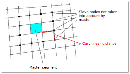
For self-impact contact, when Curvilinear Distance (from a node of the master segment to a slave node) is smaller than
If the friction flag Ifric = 0 (default), the old static friction formulation is used:
Whilem Tinterface is the temperature which is taken as the mean temperature of slave and master:
For flag Ifric > 0, new friction models are introduced. In this case, the friction coefficient is set by a function ( Where, p is the pressure of the normal force on the master segment and V is the tangential velocity of the slave node.
The following formulations are available:
where,
First critical velocity First critical velocity The static friction coefficient C1 and the dynamic friction coefficient C2, must be less than the maximum friction C3 ( The minimum friction coefficient C4 must be less than the static friction coefficient C1 and the dynamic friction coefficient C2 ( If Ifiltr flag ≠ 0, the tangential forces are smoothed using a filter:
Where if Ifiltr = 1 if Ifiltr = 2 if Ifiltr = 3 The filtering coefficient Xfreq should have a value between 0 and 1. If Iform = 1 (default) viscous formulation, the friction forces are:
While an adhesion force is computed as:
If Iform = 2, stiffness formulation), the friction forces are:
While an adhesion is computed as:
Where, Vt is the contact tangential velocity. Iform = 2 is recommended for implicit and low speed impact explicit analysis. By Ithe =1 (heat transfer activated) to consider heat exchange and heat friction in contact.
Tint is used only when Ithe_form= 0. In this case. The temperature of master side assumed to be constant (equal to Tint). If Ithe_form=1, then Tint is not take into account. So the nodal temperature of master side will be considered. Heat exchange coefficient
While fK is the function of fct_IDK.
When both Fheats and Fheatm are equal to 0, the conversion of the frictional sliding energy to heat is not activated.
Radiation is considered in contact if
While Drad is the Maximum distance for radiation computation. The default value for Drad is computed as the maximum of:
It is recommended not to set the value too high for Drad, which may reduce the performance of RADIOSS Engine. A radiant heat transfer conductance is computed as:
with
Where,
|
See Also:
Interface type 7 in User's Guide
Penalty Method in User's Guide
Interface type 7 in Theory Manual
Example 9.1 - Billiards (pool)


 , where
  , where
  for truss and beam elements, with
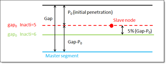
 if
if 
 if
if , standard -3dB filter, with
  , and
, and 
 (
(