|
»Click here to display Table of Contents«
|

Example 3 - S-beam Crash |

|

|

|

|
|
Example 3 - S-beam Crash |
|
|
|

|
|
»Click here to display Table of Contents«
|
Example 3 - S-beam Crash |
|
|
|
|
|
Example 3 - S-beam Crash |
|
|
|
|
A sensitive study is performed on a crushed S-beam. The modeling includes a material law using the elasto-plastic model of Johnson-Cook and an self-impacting interface based on the Penalty method in order to model the buckling of the beam. An initial velocity is applied on the left section via a kinematic condition: either a rigid body or a rigid link. The impacting condition is sliding and is secured by specific boundary conditions in the right section. Half of the structure is modeled.
The results are compared according to three different views:
| • | Shell element formulations (BATOZ, QEPH and BT hourglass type 3) |
| • | Plasticity options (global and progressive plasticity) |
| • | Influence of the initial velocity (5 and 10 ms-1) |
Several criteria are used to compare the results:
| • | Deformation configuration |
| • | Crushing force versus displacement (via momentum integration) |
| • | Energy assessment |
| • | Displacement of the left section |
| • | Hourglass energy |
| • | Kinetic energy |
| • | Internal energy |
| • | Maximum force |
| • | Maximum plastic strain |
BATOZ and QEPH element formulations provide accurate results. The BT hourglass type 3 formulation is a low-cost method and the QEPH formulation provides a good precision/cost ratio (the cost is three times lower than the BATOZ formulation). BATOZ and QEPH are element formulations which do not have hourglass energy.
The results show an over-estimation of the plastic strain in the case of the global plasticity use.
TitleS-Beam |
|
||||||
Number3.1 |
|||||||
Brief DescriptionAn S-beam is crushed against a rigid wall with initial velocity. |
|||||||
Keywords
|
|||||||
RADIOSS Options
|
|||||||
Input FileQEPH: <install_directory>/demos/hwsolvers/radioss/03_S-Beam/QEPH/Global_plasticity/QEPH* BATOZ: <install_directory>/demos/hwsolvers/radioss/03_S-Beam/BATOZ/Global_plasticity/BATOZ* BT_type3_NiP0: <install_directory>/demos/hwsolvers/radioss/03_S-Beam/BT-type3/Global_plasticity/Q4_NIP0* BT_type3_NiP5: <install_directory>/demos/hwsolvers/radioss/03_S-Beam/BT-type3/NiP5/Q4_NIP5* |
|||||||
Technical / Theoretical LevelAdvanced |
|||||||
The purpose of this example is to study the behavior of a crashed S-beam using various shell formulations and a number of different integration points. This test also compares the initial velocity influence on results. A MODIF file is used to introduce an self-impacting interface.
An S–beam is crushed at an initial rate of 5 ms-1 against a rigid wall. The section is an empty square-shaped tube (each side measuring 80 mm). The thickness is 1.5 mm. The tube is made of steel, and plasticity is taken into account, but not failure. Using symmetry, half of the cross-section is modeled.
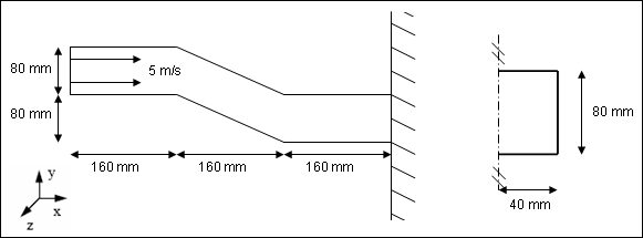
Fig 1: Problem description and beam cross-section.
The following system is used: mm, ms, g, N, MPa
The material used follows an isotropic elasto-plastic Johnson-Cook law.
Material properties:
| • | Young’s modulus: 199355 MPa |
| • | Poisson’s ratio: 0.3 |
| • | Density: 7.9x10⁻³ g/mm3 |
| • | Yield stress: 185.4 MPa |
| • | Hardening parameter: 540 MPa |
| • | Hardening exponent: 0.32 |
| • | Maximum stress: 336.6 MPa |
All other properties are set to the default values.
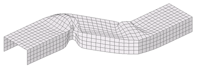
The mesh is a regular shell mesh. Each shell measures approximately 10 mm x 10 mm.
A sensitive study is performed on:
| • | Shell element formulations: BATOZ, QEPH and Belytschko hourglass type 3 |
| • | Plasticity options: global and progressive plasticity model |
| • | Influence of the initial velocity: 5 and 10 ms-1 |

Fig 2: Structure’s overall mesh
The rigid wall is modeled with boundary conditions on the right section of the beam (X, Z translations and all rotations fixed).
The left section undergoes the following conditions:
| • | Fixed in the Z direction. |
| • | Initial velocity of 5 m/s in the X direction. |
| • | All nodes are rigidly connected in X, Y and Z directions. |
| • | A 500 Kg mass is added on the left end. |
Block format input specifications:
| • | Hierarchy organization: there is only one subset made up of three parts, one for each side of the beam, and one for the top. The materials and properties are identical for each part. |
| • | Node groups: there are three node groups, one for each end of the beam, and one for the symmetry plane. The boundary conditions are set on the left end. |
| • | TH selection: DX is saved for node 1 (the node used to display displacement at the left end). |
Taking account of symmetry, half of the structure is modeled. The symmetry plane covers the y axis = 0 mm. Boundary conditions are also set at the right end to simulate a rigid wall (slide).
Two equivalent possibilities are available for generating kinematic conditions attached to the left extremity of the beam. The first consists of creating a rigid body to connect all of the left section nodes to the gravity center of the beam cross-section, with a mass being introduced on a master node. The second type of modeling retained uses the rigid link option, which rigidly connects the left section nodes in the X, Y and Z directions. A 500 kg mass is added to the master node.
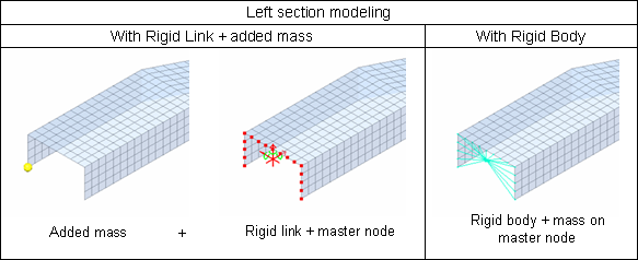
Both models provide identical results; the rigid link will be used for this example.
| • | An initial velocity of 5 ms-1 is used for the master node of the rigid link or for the rigid body. |
| • | MODIF file: |
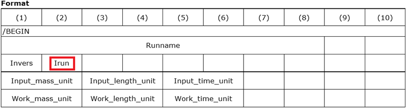
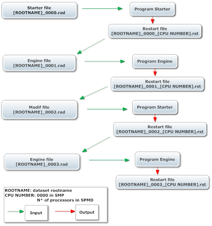
A MODIF file enables to add option(s) during a run. The MODIF files carry the name ROOTNAMErun*.rad. Where, run# is the RADIOSS run number four digits from 0000 to 9999 and run# is the name of the last Restart file + 1.
For example, to run a MODIF file after the first run (restart file ROOTNAME_0001.rad), the run number for the MODIF file must be 2: ROOTNAME_0002.rad. MODIF files use the same inout format as the RADIOSS deck. Put all the input decks in one folder and with Irun=2 RADIOSS will automatically recognize the MODIF file.
After 20 ms, an self-impacting interface is required to deal with the buckling of the beam. This is added using a MODIF file where the interface is defined and saved for the TH. This type of interface corresponds to 7; all values are set to "default". To define the master side, a surface is defined using three parts of the model (/SURF/PART). The safest and easiest method for defining the slave side of an self-impacting interface consists of defining a node group with the master surface (/GRNOD/SURF).
The MODIF file is ROOTNAME_0002.rad.
The next Engine file is ROOTNAME_0003.rad (final time = 30 ms).
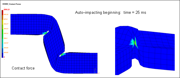
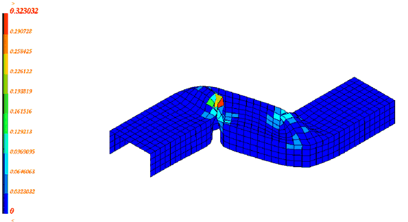
Fig 3: Contact force at the start of self-impacting.
The MODIF file options used in Engine file ROOTNAME_0002.rad are:
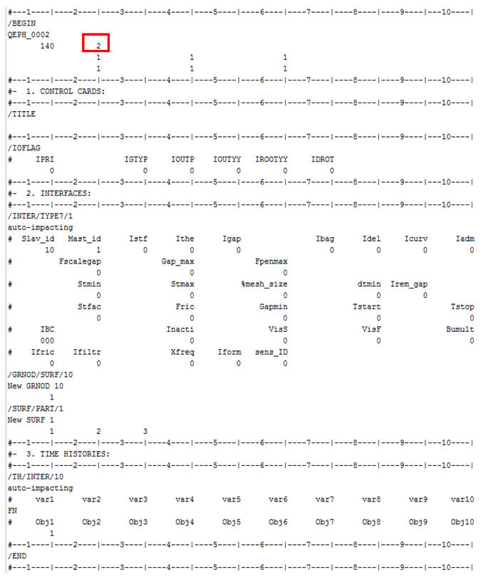
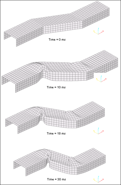
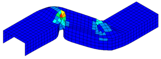
Fig 4: Deformed mesh for Belytschko hourglass type 3 formulation (V=5 m.s-1)
The crushing force is obtained by time derivation of the X-momentum. The maximum displacement over a 20 ms long computation corresponds to 96.4 mm.
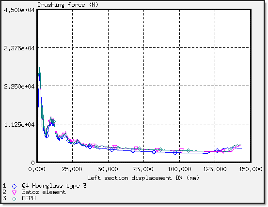
Fig 5: Crushing force (X-direction) versus displacement for different element formulations (V=5 m.s-1)
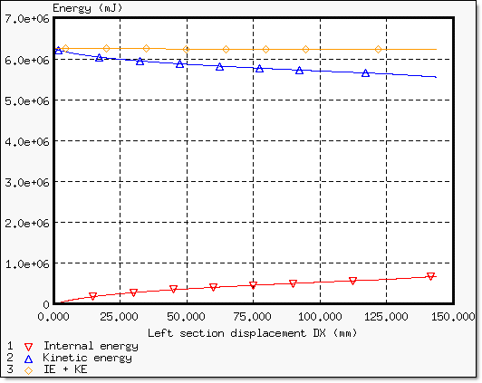
Fig 6: Energy assessment for Belytschko hourglass type 3 (V=5 m.s-1).
The structure does not absorb a lot of energy and that you should check the hourglass energy, which may be relatively high compared with the total energy.
The following table shows the results obtained using different element formulations and plasticity options:
|
Global plastification (NiP = 0) |
NiP = 5 |
||
|---|---|---|---|---|
BATOZ |
QEPH |
Q4 Hourglass type 3 |
Q4 Hourglass type 3 |
|
Initial energy (mJ) |
6.25012x10⁶ |
6.25012x10⁶ |
6.25012x10⁶ |
6.25012x10⁶ |
Kinetic energy (mJ) t = 30 ms |
5.499x10⁶ (0.877) |
5.47964x10⁶ (0.875) |
5.55602x10⁶ (0.889) |
5.55641x10⁶ (0.888) |
Internal energy (mJ) t = 30 ms |
750374 (0.123) |
770384 (0.125) |
684100 (0.109) |
691255 (0.110) |
Hourglass energy (mJ) t = 30 ms |
0 |
0 |
28385 (0.0016) |
33341.6 (0.002) |
Displacement (mm) t = 30 ms |
144.0 |
144.6 |
144.6 |
144.7 |
CPU (Normalized) |
1.082 |
0.99 |
1 |
0.988 |
Error on energy (%) t = 30 ms |
0% |
0% |
-0.1% |
-0.1% |
Maximum force (N) |
42459.4 |
42688.5 |
35949.4 |
35387.2 |
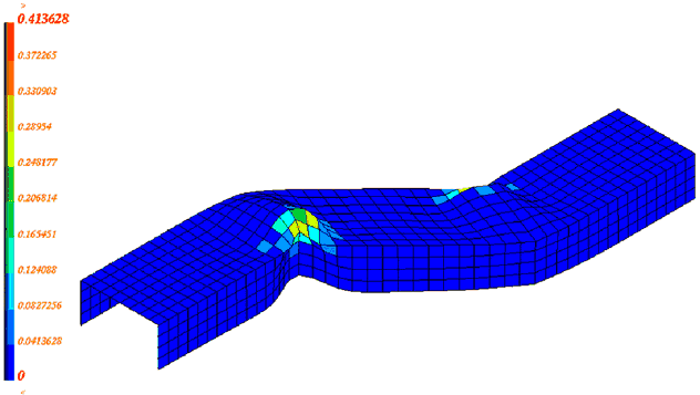
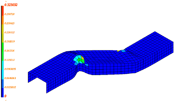
Maximum plastic strain |
0.462 |
0.448 |
0.414 |
0.323 |
Initial velocity = 5 ms-1 (Values in brackets are the energy percentages compared with the initial energy)
Plastic Strain - Time = 10.00 ms |
|---|
Global plastification
|
Progressive plastification (Nip = 5)
|
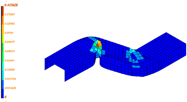
Plastic Strain - Time = 30.00 ms |
Global plastification
|
Progressive plastification (Nip = 5)
|
The following table indicates the influence of the crushing velocity (5 ms-1 and 10 ms-1).
|
Initial Velocity = 5 ms-1 |
Initial Velocity = 10 ms-1 |
|---|---|---|
Initial energy (mJ) |
6.25012x10⁶ |
2.5 x10⁷ |
Kinetic energy (mJ)
X – displacement = 70 mm: X – displacement = 140 mm: |
5.79897x10⁶ (0.928) 5.57192x10⁶ (0.891) |
2.44581x10⁷ (0.978) 2.41546 x10⁷ (0.966) |
Internal energy (mJ)
X – displacement = 70 mm: X – displacement = 140 mm: |
444848 (0.0711) 666704 (0.107) |
538142 (0.0215) 840622 (0.0336) |
Hourglass energy (mJ)
X – displacement = 70 mm: X – displacement = 140 mm: |
4879.87 (0.0009) 9530.27 (0.002) |
5969.83 (0.0005) 12702.4 (0.0004) |
Maximum force (N) |
35949.4 |
41704.3 |
Error on energy (%) |
-1.09% |
-1.11% |
(Values in brackets refer to the energy percentages compared with the initial energy)
BT hourglass type 3 formulation is used in this section.
The amount of internal energy stored in the beam during a crash is relatively higher when the initial velocity is set to 10 ms-1, instead of 5 ms-1. The hourglass energy is quite low with either initial velocity.
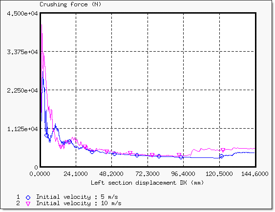
Fig 7: Crushing force versus displacement for the different initial velocities
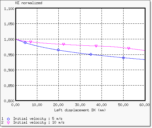
Fig 8: Kinetic energy normalized for the different initial velocities ![]()
First self-contact:
| • | Initial velocity = 5 ms-1: displacement = 120 mm; |
| • | Initial velocity = 10 ms-1: displacement = 94.15 mm. |