|
»Click here to display Table of Contents«
|

Example 4 - Airbag |

|

|

|

|
|
Example 4 - Airbag |
|
|
|

|
|
»Click here to display Table of Contents«
|
Example 4 - Airbag |
|
|
|
|
|
Example 4 - Airbag |
|
|
|
|
This example deals with the deployment of a chambered airbag modeled by monitored volumes using communications. The airbag is initially folded along four fold lines. The fabric is meshed with shell elements which undergo an elastic orthotropic behavioral test. Perfect gas is injected into a central chamber via an inflator with the air flow through the connected chambers being simulated. The chambers inflate while the airbag is deploying.
In the self-impacting interface definition, the action of the Inacti flag to deactivate stiffness in the case of initial penetration is studied in order to significantly increase the time step. An adequate gap enables to pass from a kinematic interface time step to a higher element time step.
TitleAirbag |
|
||||||
Number4.1 |
|||||||
Brief DescriptionA chambered airbag folded along four fold lines is deployed. |
|||||||
Keywords
|
|||||||
RADIOSS Options
|
|||||||
Input FileInactiv_0_Gap0.1: <install_directory>/demos/hwsolvers/radioss/04_Airbag/Inacti0_Gap01/AIRFIX* Inactiv_5_Gap0.3: <install_directory>/demos/hwsolvers/radioss/04_Airbag/Inacti5_Gap03/AIRBAG* Inactiv_5_Gap1.5: <install_directory>/demos/hwsolvers/radioss/04_Airbag/Inacti5_Gap15/AIRBAG2* |
|||||||
Technical / Theoretical LevelBeginner |
|||||||
The purpose of this example is to deal with monitored volumes using communications on a simple airbag model. Methods for increasing the time step are considered.
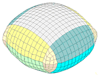
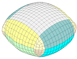
A 30-liter airbag is folded along the four fold lines. The following examples illustrate the airbag folded and deployed.
| Fig 1: Folded airbag | Fig 2: Deployed airbag |
The fabric thickness is 0.33 mm and is modeled using an elastic orthotropic material law (/MAT/LAW19) with the following properties:
| • | Density: 0.85x10⁻³ g/mm3 |
| • | Young’s Modulus: 500 MPa in both directions |
| • | Shear Modulus: 10 MPa |
| • | Reduction factor: 0.001 |
The property set is /PROP/SH_ORTH (shell orthotropic, type 9), using one integration point.
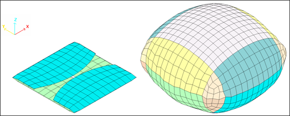
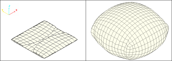
Fig 3: Overall mesh of the structure (folded and deployed).
The model is divided into two subsets: the fabric layers and the communication surfaces.
The fabric surface is then divided into 9 subsets, one for each monitored volume. Each "monitored volume" is further divided into two parts. All the parts of the layer of fabric have the same Type and MID.
The same properties apply for the communication surfaces.
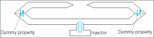
Fig 4: Folder airbag with communications.
The airbag is modeled using 9 communicating volumes in order to simulate the air flow through the folds and the behavioral differences within the airbag when unfolding. The communicating surfaces between the volumes are simulated using dummy membranes. The dummy membranes are modeled using shells with fictitious material (/MAT/LAW0).
The main properties for this type are:
| • | Volumetric damping factor: 0.001 g.mm-1ms-1 . |
| • | External pressure: 0.1 MPa |
| • | Constant perfect gas: 1.4 |
| • | Specific heat at constant pressure: 926 mJ/g (This is the specific heat coefficient related to mass) |
| • | Temperature: 780 K. |
| • | Communication area: total (Acom =1 and Scom =0) |
| • | Time to deflate vent hole: 1030 ms |
The gas molecular weight and specific heat coefficients are defined in /MAT/GAS (using MASS type):
| • | Molecular weight of gas MW: 30.09204 g/kmol (AIR) |
| • | Specific heat at constant pressure: 926 mJ/g (specific heat coefficient related to mass) |
Specific input for the central chamber one (inflator):
| • | Vent hole membrane surface area is 1000 mm2 (Avent =0) and is immediately activated. |
| • | Relative vent deflation pressure: 0.0002 |
| • | Number of injectors: 1 (Njet =1; Ijet =0) |
Using /PROP/INJECT1 to described mass inject:
| • | Final injected mass is 46 g injected into the central chamber (FscaleM and FscaleT =1). Two functions define the mass and temperature of the injected gas compared with time (function identifiers: fct_IDM and fct_IDT). |
Time (ms) |
0 |
2 |
4 |
5 |
6 |
8 |
11 |
12 |
15 |
19 |
28 |
30 |
106 |
Mass (g) |
0 |
6 |
11 |
14 |
17 |
22 |
29 |
31 |
36 |
41 |
45 |
46 |
46 |
Injected mass function.
Time (ms) |
0 |
106 |
Temperature (K) |
780 |
780 |
Temperature of injected gas function.
Taking into account the fabric is self-impacting with itself, an self-impacting interface must be used. The interface’s Block Format definition is made: defining the master surface (/SURF/PART), then defining the slave nodes for all nodes on this surface (/GRNOD/SURF).
The distance between the fabric layers before unfolding is very small. In order to avoid initial penetration, the gap required is approximately 0.1 mm, thus enabling the time step to considerably decrease when such a gap is chosen.
By using Inacti =5, a 0.3 mm gap is chosen. Any initial penetration below 0.2 mm (two-thirds of the input gap) is ignored (it is strongly recommended to verify that no initial penetration is above this value).
In order to demonstrate the interest of the Inacti flag, the same model was run with Inacti at a value of 0, with a gap of 0.1 mm (no initial penetration).
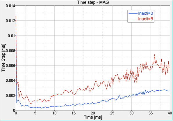
Fig 5: Comparison between option Inacti = 5 and Inacti = 0
Using Inacti = 5, the minimum time step is around 10-3 ms. When not using this option, the minimum time step is around 2x10⁻⁴ ms. For the full model, the number of cycles may be divided up into 10 or more. Furthermore, the model is numerically less sensitive.
The time step is monitored by the interface time step (kinematic) for up to 40 ms despite the unfolding and the fact that there is no energy contact from 7.8 ms. In order to transfer into the element time step and to reduce computation time, it is advisable to increase the gap so the kinematic step becomes higher than the element step.
Time-stepkinetic < 0.9 x GAP / Nodal_velocityrelative (using scale factor = 0.9)
The time step is only low during the unfolding phase (before 10 ms) with a gap equal to 1.5 mm.
|
Inacti flag = 5 |
Inacti flag = 0 |
|
|---|---|---|---|
GAP = 0.3 mm |
GAP = 1.5 mm |
GAP = 0.1 mm |
|
Error on energy |
-16.3% |
-19.6% |
-15.5% |
Elapsed Time [s] |
57.5 |
47.8 |
78.58 |
Airbag deploy |
completely deploy |
completely deploy |
incompletely deploy |
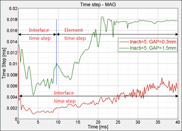
Fig 6: Time step obtained with GAP = 0.3 mm and GAP = 1.5 mm (Inacti = 5).
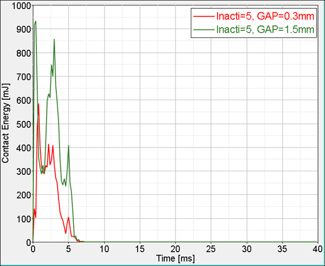
Fig 7: Contact energy with GAP = 0.3 mm and GAP = 1.5 mm (Inacti = 5).
It is obvious that a gap of 1.5 mm generates an increase in the contact force. However, the additional error on energy remains quite low and is acceptable.
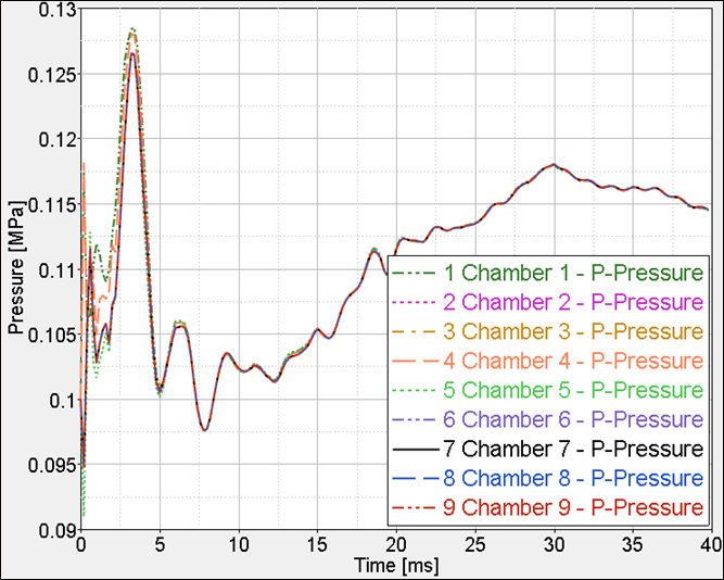
Fig 8: Time history of pressure.
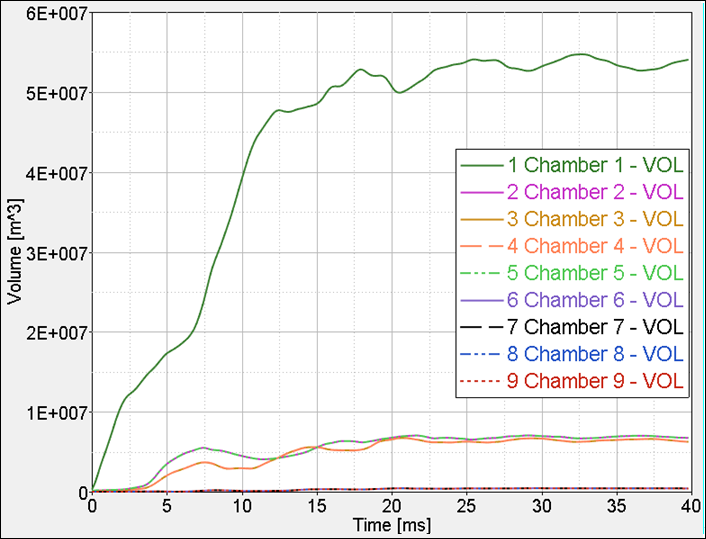
Fig 9: Time history of volume.
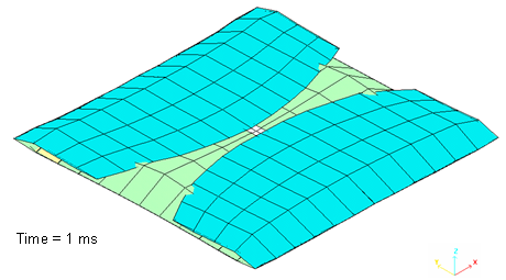
Fig 10: Central chamber is inflating.
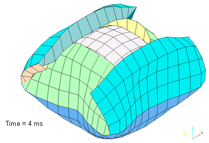
Fig 11: All chambers are inflating.
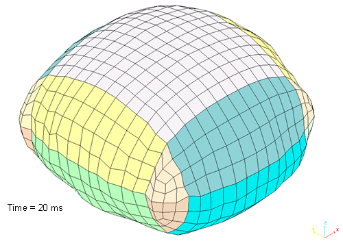
Fig 12: Airbag is deployed