HyperWorks Solvers

/MONVOL/COMMU1

/MONVOL/COMMU1

Previous topic Next topic Expand/collapse all hidden text  

/MONVOL/COMMU1

Previous topic Next topic JavaScript is required for expanding text JavaScript is required for the print function  

Block Format Keyword

/MONVOL/COMMU1 - Hybrid Airbag with Communications

Description

Describes multi-chambered airbag with hybrid input of injected gas. This keyword is similar to /MONVOL/COMMU, but has more flexible input.

Gas materials can be specified in separate /MAT/GAS cards
Injector can be specified in separate /PROP/INJECT for injector
Scaling of communication area between airbag chambers as function of time or relative pressure is possible

Format

(1)

(2)

(3)

(4)

(5)

(6)

(7)

(8)

(9)

(10)

/MONVOL/COMMU1/monvol_ID/unit_ID

monvol_title

surf_IDex


Hconv


Ascalet

AscaleP

AscaleS

AscaleA

AscaleD

mat_ID


Pext

T0

Iequi

Ittf


Number of injectors

(1)

(2)

(3)

(4)

(5)

(6)

(7)

(8)

(9)

(10)

Njet


For each injector

(1)

(2)

(3)

(4)

(5)

(6)

(7)

(8)

(9)

(10)

inject_ID

sens_ID

Ijet

node_ID1

node_ID2

node_ID3


Jetting function data (read only if Ijet = 1)

(1)

(2)

(3)

(4)

(5)

(6)

(7)

(8)

(9)

(10)

fct_IDPt

fct_IDPclip0556

fct_IDPsymbol_s


FscalePt

FscalePclip0556

FscalePsymbol_s


Define Nvent vent holes and Nporsurf porous fabric surfaces

(1)

(2)

(3)

(4)

(5)

(6)

(7)

(8)

(9)

(10)

Nvent

Nporsurf


For each vent hole

(1)

(2)

(3)

(4)

(5)

(6)

(7)

(8)

(9)

(10)

surf_IDv

Iform

Avent

Bvent


vent_title

Tstart

Tstop


IdtPdef

fct_IDt

fct_IDP

fct_IDA


Fscalet

FscaleP

FscaleA

fct_IDt

fct_IDP'

fct_IDA'


Fscalet'

FscaleP'

FscaleA'


Insert for each porous surface

(1)

(2)

(3)

(4)

(5)

(6)

(7)

(8)

(9)

(10)

surf_IDps

Iformps

Iblockage


surface_title

Tstart

Tstop


IdtPdef


Insert only if Iformps =0

(1)

(2)

(3)

(4)

(5)

(6)

(7)

(8)

(9)

(10)

Cps

Areaps

fct_IDcps

fct_IDaps

Fscalecps

Fscaleaps


Chemkin model date (insert only if Iform = 2 or Iformps =2)

(1)

(2)

(3)

(4)

(5)

(6)

(7)

(8)

(9)

(10)

fct_IDv


Fscalev


Number of communicating airbags

(1)

(2)

(3)

(4)

(5)

(6)

(7)

(8)

(9)

(10)

Nbag


Define Nbag communicating airbags (two lines per communicating airbag)

(1)

(2)

(3)

(4)

(5)

(6)

(7)

(8)

(9)

(10)

bag_ID

surf_IDc

Acom

Tcom

fct_IDCt

fct_IDCP

FscaleCt

FscaleCP


hmtoggle_plus1Flag Definition

Field

Contents

SI Unit Example

monvol_ID

Monitored volume identifier

(Integer, maximum 10 digits)


unit_ID

Optional unit identifier

(Integer, maximum 10 digits)


monvol_title

Monitored volume title

(Character, maximum 100 characters)


surf_IDex

External surface identifier

(Integer)


Hconv

Heat transfer coefficient (Comment 23)

(Real)

Ascalet

Abscissa scale factor for time based functions

Default = 1.0  (Real)

AscaleP

Abscissa scale factor for pressure based functions

Default = 1.0  (Real)

AscaleS

Abscissa scale factor for area based functions

Default = 1.0  (Real)

AscaleA

Abscissa scale factor for angle based functions

Default = 1.0  (Real)

AscaleD

Abscissa scale factor for distance based functions

Default = 1.0  (Real)

mat_ID

Material identifier for initial gas (/MAT/GAS)

(Integer)


Volumetric viscosity

Default = 0.01  (Real)


Pext

External pressure

(Real)

T0

Initial temperature

Default = 295K (Real)

Iequi

Initial thermodynamic equilibrium flag

(Integer)

= 0: The mass of gas initially filling the airbag is determined with respect to the volume at time zero.

= 1: The mass of gas initially filling the airbag is determined with respect to the volume at beginning of jetting (Comment 6).


Ittf

Time shift flag

(Integer)

Only active when at least one injection sensor is specified. Determines time shift for venting, porosity and communication options when injection starts at a Time to Fire specified in a sensor.

Flag values= 0 (default), 1 and 2 (obsolete), and 3 (all options are shifted) are described in details in Comment 17.


Njet

Number of injectors

(Integer)


inject_ID

Injector property identifier

(Integer)


sens_ID

Sensor identifier

(Integer)


Nvent

Number of vent holes

(Integer)


surf_IDv

Vent holes membrane surface identifier

(Integer)


Iform

Formulation flag

(Integer)

= 0: Default set to 1

= 1: Isenthalpic (Default)

= 2: Chemkin

= 3: Isenthalpic with possible gas (mat_ID) flow in


Avent

if surf_IDv 0: scale factor on surface
Default = 1.0 (Real)
 

if surf_IDv = 0: surface of vent holes
Default = 0.0 (Real)


Bvent

if surf_IDv 0: scale factor on impacted surface
Default = 1.0 (Real)
 

if surf_IDv = 0: Bvent is reset to 0
Default = 0.0 (Real)


vent_title

Vent hole title

(Character, maximum 20 characters)


Tstart

Start time for venting

Default = 0  (Real)

Tstop

Stop time for venting

Default = 1030  (Real)

Pressure difference to open vent hole membrane

Default = 0  (Real)

Minimum duration pressure exceeds Pdef to open vent hole

Default = 0 (Real)

IdtPdef

Time delay flag when is reached:

(Integer)

= 0: pressure should be over during a cumulative time to activate venting

= 1: venting is activated after is reached


fct_IDt

Porosity vs time function identifier

(Integer)


fct_IDP

Porosity vs pressure function identifier

(Integer)


fct_IDA

Porosity vs area function identifier

(Integer)


Fscalet

Scale factor for fct_IDt

Default = 1.0  (Real)


FscaleP

Scale factor for fct_IDP

Default = 1.0  (Real)


FscaleA

Scale factor for fct_IDA

Default = 1.0  (Real)


Ijet

Jetting flag

(Integer)

= 0: no jetting

= 1: jetting


node_ID1, node_ID2, node_ID3

Node identifiers N1, N2, and N3 for jet shape definition

(Integer)


fct_IDPt

Identifier of the function number defining

(Integer)


fct_IDPclip0556

Identifier of the function number defining

(Integer)


fct_IDPsymbol_s

Identifier of the function number defining

(Integer)


FscalePt

Scale factor for fct_IDPt

Default = 1.0  (Real)

FscalePclip0556

Scale factor for fct_IDPclip0556

Default = 1.0  (Real)

FscalePsymbol_s

Scale factor for fct_IDPsymbol_s

Default = 1.0  (Real)

fct_IDv

Outflow velocity function identifier, Chemkin model

(Integer)


Fscalev

Scale factor on fct_IDv

Default = 1.0  (Real)

fct_IDt’

Porosity vs time function identifier

(Integer)


fct_IDP’

Porosity vs pressure function identifier

(Integer)


fct_IDA’

Porosity vs impacted surface function identifier

(Integer)


Fscalet’

Scale factor for fct_IDt’

Default = 1.0  (Real)


FscaleP'

Scale factor for fct_IDP’

Default = 1.0  (Real)


FscaleA'

Scale factor for fct_IDA’

Default = 1.0  (Real)


Nporsurf

Number of porous surfaces

(Integer)


surf_IDps

Porous surface identifier (ignored if Iformps = 0)

(Integer)


Iformps

Porosity formulation

(Integer)

= 0: Bernouilli (Wang & Nefske) (no dependence on fabric material)

= 1: Bernouilli (Wang & Nefske)

= 2: Chemkin

= 3: Graefe


Iblockage

Block leakage flag, if contact (Iformps > 0)

(Integer)

= 0: no

= 1: yes


surface_title

Porous surface title

(Character, maximum 20 characters)


Cps

Scale factor on leakage area (Iformps =0)

(Real)


Areaps

Leakage area (Iformps=0)

(Real)

fct_IDcps

Function identifier defining Cps(t), ignored if Cps is not equal to zero.

(Integer)


fct_IDaps

Function identifier defining Areaps(P-Pext), ignored if Areaps is not equal to zero.

(Integer)


Fscalecps

Scale factor for fct_IDcps

Default = 1 (Real)


Fscaleaps

Scale factor for fct_IDaps

Default = 1 (Real)

Nbag

Number of communicating airbags

(Integer)


bag_ID

Airbag identifier (Comment 20)

(Integer)


surf_IDC

Communicating surface identifier

(Integer)


Pressure difference to open communication surface membrane

(Real)

Acom

if surf_IDC = 0: communicating surface

if surf_IDC ≠ 0: scale factor on surface

Default = 1.0  (Real) (Comment 22)


Tcom

Start time for communication

(Real)

Minimum duration pressure difference exceeds to open communication surface membrane

(Real)

fct_IDCt

Communicating surface vs time function identifier

(Integer)


fct_IDCP

Communicating surface vs relative pressure function identifier

(Integer)


FscaleCt

Scale factor for fct_IDCt

Default = 1.0 (Real)


FscaleCP

Scale factor for fct_IDCP

Default = 1.0 (Real)


hmtoggle_plus1Comments
1.The airbag external surface should be built only from 4- and 3- noded shell elements. The airbag external surface cannot be defined with /SURF/SEG, nor with /SURF/SURF, if a sub-surface is defined in /SURF/SEG.
2.The volume must be closed and the normals must be oriented outwards.
3.Abscissa scale factors are used to transform abscissa units in airbag functions, for example:

where, t is the time and ft is the function of fct_IDt.

Where, P is the pressure and fP is function of fct_IDP. The options are obsolete. Normally, the curve scaling parameters are used instead.

4.Pressure and temperature of external air and the initial pressure and temperature of air inside of airbag is set to Pext and T0.
5.The characteristics of the gas initially filling the airbag (temperature and pressure) must be defined (no default) and must be equal for each communicating airbag.
6.Initial thermodynamic equilibrium is written at time zero (Iequi =0) or at beginning of jetting (Iequi =1), based on the following equation with respect to the volume at time zero, or the volume at beginning of jetting:

Where, M0 is the mass of gas initially filling the airbag, Mi is the molar mass of the gas initially filling the airbag, and R is the gas constant depending on the units system given the in /BEGIN card. For example in SI system:

7.If jetting is used, an additional pressure is applied to each element of the airbag:

Function is automatically shifted by time given in sensor, which activates injection.

8.With m being the normalized vector between the projection of the center of the element upon segment (N1 and N3) and the center of the element; the angle between vectors MN2 and m (in degrees), is the distance between the center of the element and its projection upon segment (N1 and N3).

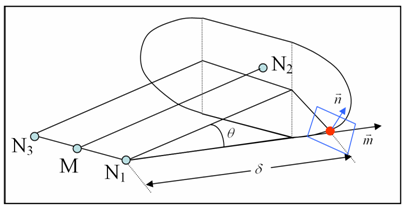
The projection of a point upon segment (N1 and N3) is defined as the projection of the point in direction MN2 upon the line (N1 and N3) if it lies inside the segment (N1 and N3). If this is not the case, the projection of the point upon segment (N1 and N3) is defined as the closest node N1 or N3 (see following figure: dihedral shape of the jet).

clip0087

with M between of N1 and N3

9.If node_ID3 = 0, node_ID3 is set to node_ID1 and the dihedral shape is reduced to a conical shape.
10.If fct_IDv = 0: isenthalpic outflow is assumed, otherwise Chemkin model is used and outflow velocity is:

with fv is function of fct_IDv

Isenthalpic model

Venting or the expulsion of gas from the volume is assumed to be isenthalpic.

The flow is also assumed to be unshocked, coming from a large reservoir and through a small orifice with effective surface area, A.

Conservation of enthalpy leads to velocity, u at the vent hole. The Bernouilli equation is then written as:

(monitored volume) (vent hole)

Applying the adiabatic conditions:

(monitored volume) (vent hole)

Where, P is the pressure of gas into the airbag and is the density of gas into the airbag.

Therefore, the exit velocity is given by:

For supersonic flows the outlet velocity is determined as described in 10.4.4.1 of the Theory Manual.

The mass out flow rate is given by:

The energy flow rate is given by:

Where, V is the airbag volume and E is the internal energy of gas into the airbag.

Chemkin model

Where, is the density of the gas within the airbag and fv is the function of fct_IDv

11.Vent holes surface is computed as follows:


with impacted surface:

and non-impacted surface:

Image12

where for each element e of the airbag materials nc(e) means the number of impacted nodes among the n(e) nodes defining the element and Ae is the area of element e.

And,

A0 is the initial area of surface surf_IDv

ft, fP and fA are functions of fct_IDt, fct_IDP and fct_IDA

ft’, fP’ and fA are functions of fct_IDt’, fct_IDP’ and fct_IDA’

12.Functions fct_IDt' and fct_IDP' are assumed to be equal to 1, if they are not specified (null identifier).
13.Function fct_IDA' is assumed as:

if it is not specified.

14.To account for contact blockage of vent holes and porous surfaces, flag IBAG must be set to 1 in the correspondent interfaces (Line 3 of interface TYPE7 or TYPE23). If not, the nodes impacted into the interface are not considered as impacted nodes in the previous formula for Aimpacted and Anon_impacted.
15.Vent holes and interchamber components should be included into the airbag (chamber) external surface.
16.When there is no sensor which activates gas injection, the vent holes and porosity becomes active, if time T becomes greater than the Tstart or if the pressure P exceeds Pdef value longer than the time given in .
17.When at least one of the injectors is activated by the sensor, then activation of venting, porosity and communication options is controlled by Ittf.

Tinj is the time of the first injector to be activated by the sensor.

Ittf = 0:


Venting, Porosity

Communication

Activation

When  longer than the time , or

When longer than the time , or

Deactivation

Tstop

N/A

Time dependent functions

No shift

No shift

Ittf = 3:


Venting, Porosity

Communication

Activation

When and P > longer than the time , or

When and longer than the time , or

Deactivation

N/A

Time dependent functions

Shifted by

Shifted by

All other related curves are active when the corresponding venting, porosity or communication option is active.

The variety of Ittf values comes from historical reasons. Values Ittf =1 and 2 are obsolete and should not be used. Usual values are Ittf =0 (no shift) or Ittf =3 (all relative options are shifted by Tinj).

18.Leakage by porosity formulations; the mass flow rate flowing out is computed as:
Iformps = 0 (Isentropic - Wang Nefske)
 
with
 

and
 
or
 
Note that the effective venting area Aeff does not vary with different airbag fabric materials.
Iformps > 0, the effective venting area Aeff is computed according to the input in the /LEAK/MAT input for fabric materials of TYPE19 or TYPE58.
Iformps = 1 (Isentropic - Wang Nefske)
Iformps = 2        

 
where ratio is the outflow gas velocity (Chemkin)

Iformps = 3         (Graefe)
19.If leakage blockage is activated, Iblockage=1, the effective venting area is modified as follows:

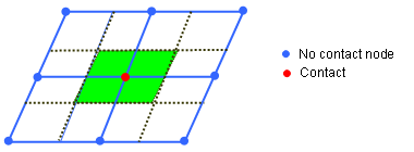
Anon_impacted is non-impacted surface (Comment 11).

The blockage will be active only if flag IBAG is set to 1 in the concerned contact interfaces (line 3 of interface TYPE7 and TYPE23).

20.It is not allowed to combine /MONVOL/COMMU and /MONVOL/COMMU1 cards in one multi-chambered airbag. However, in the same model it is possible to use different multi-chambered airbags (based on /MONVOL/COMMU or /MONVOL/COMMU1) for each airbag.
21.When there is no sensor which activates gas injection, the communication surface is open if or if the pressure exceeds during more than (Comment 17).
22.Communication surface, Scom is computed as follows:
if surf_ID =0,


if surf_ID > 0 and Area is the surface of surf_ID,

Where, is the pressure difference between the chambers and fCt and fCP are functions of fct_IDCt and fct_IDCP

23.The lost heat flow is given by:

See Also:

Airbag modeling in User's Guide

Monitored Volume type in COMMU in Theory Manual

Example 4 - Airbag