HyperWorks Solvers

/MONVOL/FVMBAG1

/MONVOL/FVMBAG1

Previous topic Next topic Expand/collapse all hidden text  

/MONVOL/FVMBAG1

Previous topic Next topic JavaScript is required for expanding text JavaScript is required for the print function  

Block Format Keyword

/MONVOL/FVMBAG1 - Airbag with Gas Flow

Description

Describes Finite Volume Method Airbag, which has more flexible input than the similar obsolete keyword /MONVOL/FVMBAG.

Gas materials are specified in separate /MAT/GAS cards.
Composition of injected gas mixture and injector properties are specified in separate /PROP/INJECT1 or /PROP/INJECT2 cards.
Automatic Finite Volume meshing in specified coordinate system, given by a frame.

Format

(1)

(2)

(3)

(4)

(5)

(6)

(7)

(8)

(9)

(10)

/MONVOL/FVMBAG1/monvol_ID/unit_ID

monvol_title

surf_IDex


Hconv


Ascalet

AscaleP

AscaleS

AscaleA

AscaleD

mat_ID


Pext

T0

Iequi

Ittf


Number of injectors

(1)

(2)

(3)

(4)

(5)

(6)

(7)

(8)

(9)

(10)

Njet


For each injector

(1)

(2)

(3)

(4)

(5)

(6)

(7)

(8)

(9)

(10)

inject_ID

sens_ID

surf_IDinj


fct_IDvel


Fscalevel


Number of vent holes and porous fabric surfaces

(1)

(2)

(3)

(4)

(5)

(6)

(7)

(8)

(9)

(10)

Nvent

Nporsurf


Define Nvent vent holes (four lines per vent hole)

(1)

(2)

(3)

(4)

(5)

(6)

(7)

(8)

(9)

(10)

surf_IDv

Iform

Avent

Bvent


vent_title

Tstart

Tstop


IdtPdef

fct_IDt

fct_IDP

fct_IDA


Fscalet

FscaleP

FscaleA

fct_IDt

fct_IDP'

fct_IDA'


Fscalet'

FscaleP'

FscaleA'


Insert for each porous surface

(1)

(2)

(3)

(4)

(5)

(6)

(7)

(8)

(9)

(10)

surf_IDps

Iformps

Iblockage


surface_title

Tstart

Tstop


Chemkin model data (read only if Iform =2 or Iformps = 2)

(1)

(2)

(3)

(4)

(5)

(6)

(7)

(8)

(9)

(10)

fct_IDV


FscaleV


Finite volume meshing parameters

(1)

(2)

(3)

(4)

(5)

(6)

(7)

(8)

(9)

(10)

frame_ID


L1

L2

L3


Nb1

Nb2

Nb3

grbric_ID

surf_IDin

Iref


Igmerg


Cgmerg

Cnmerg

Ptole


qa

qb

Hmin


Ilvout

Nlayer

Nfacmax

Nppmax

Ifvani


hmtoggle_plus1Flag Definition

Field

Contents

SI Unit Example

monvol_ID

Monitored volume identifier

(Integer, maximum 10 digits)


unit_ID

Optional unit identifier

(Integer, maximum 10 digits)


monvol_title

Monitored volume title

(Character, maximum 100 characters)


surf_IDex

External surface identifier (Comments 1 and 2)

(Integer)


Hconv

Heat transfer coefficient (Comment 24)

(Real)

Ascalet

Abscissa scale factor for time based functions

Default = 1.0  (Real)

AscaleP

Abscissa scale factor for pressure based functions

Default = 1.0  (Real)

AscaleS

Abscissa scale factor for area based functions

Default = 1.0  (Real)

AscaleA

Abscissa scale factor for angle based functions

Default = 1.0  (Real)

AscaleD

Abscissa scale factor for distance based functions

Default = 1.0  (Real)

mat_ID

Initial gas material identifier

(Integer)


Pext

External pressure

(Real)

T0

Initial temperature

Default = 295K (Real)

Iequi

Initial thermodynamic equilibrium flag

(Integer)

= 0: The mass of gas initially filling the airbag is determined with respect to the volume at time zero.

= 1: Start of the FVM simulation is shifted to TTF (time to fire) specified in an injector sensor.


Ittf

Time shift flag

(Integer)

Active only when at least one injection sensor is specified. Determines time shift for venting and porosity options when injection starts at a Time to Fire specified in a sensor.

Flag values = 0 (default), 1 and 2 (obsolete), and 3 (all options are shifted) are described in details in Comment 8.


Njet

Number of injectors

(Integer)


inject_ID

Injector property identifier

(Integer)


sens_ID

Sensor identifier

(Integer)


surf_IDinj

Injector surface identifier (must be different for each injector)

(Integer)


fct_IDvel

Injected gas velocity identifier

(Integer)


Fscalevel

Injected gas velocity scale factor

Default = 1.0  (Real)

Nvent

Number of vent holes

(Integer)


surf_IDv

Vent holes membrane surface (Real) or porous surface identifier

(Integer)


Iform

Venting formulation (Comment 6)

(Integer)

= 0: Default set to 1

= 1: Isenthalpic (default)

= 2: Chemkin

= 3: Local

= 4: Isenthalpic with possible gas (mat_ID) flow-in


Avent

if surf_IDv 0: scale factor on surface
Default = 1.0 (Real)
 

if surf_IDv = 0: surface of vent holes
Default = 0.0 (Real)


Bvent

if surf_IDv 0: scale factor on impacted surface
Default = 1.0 (Real)
 

if surf_IDv = 0: Bvent is reset to 0
Default = 0.0 (Real)


vent_title

Vent hole title

(Character, maximum 20 characters)


Tstart

Start time for venting

Default = 0  (Real)

Tstop

Stop time for venting

Default = 1030  (Real)

Pressure difference to open vent hole membrane ()

Default = 0  (Real)

Minimum duration pressure exceeds Pdef to open vent hole membrane

Default = 0  (Real)

fct_IDV

Outflow velocity function identifier

(Integer)


FscaleV

Scale factor on fct_IDV

Default = 1.0  (Real)

IdtPdef

Time delay flag when is reached:

(Integer)

= 0: pressure should be over during a cumulative time to activate venting

= 1: venting is activated after is reached


fct_IDt

Porosity vs time function identifier

(Integer)


fct_IDP

Porosity vs pressure function identifier

(Integer)


fct_IDA

Porosity vs area function identifier

(Integer)


Fscalet

Scale factor for fct_IDt

Default = 1.0 (Real)


FscaleP

Scale factor for fct_IDP

Default = 1.0 (Real)


FscaleA

Scale factor for fct_IDA

Default = 1.0 (Real)


fct_IDt’

Porosity vs time when contact function identifier

(Integer)


fct_IDP’

Porosity vs pressure when contact function identifier

(Integer)


fct_IDA’

Porosity vs impacted surface function identifier

(Integer)


Fscalet'

Scale factor for fct_IDt’

Default = 1.0  (Real)


FscaleP'

Scale factor for fct_IDP’

Default = 1.0  (Real)


FscaleA'

Scale factor for fct_IDA’

Default = 1.0  (Real)


Nporsurf

Number of porous surfaces (Comment 15)

(Integer)


surf_IDps

Porous surface identifier

(Integer)


Iformps

Porosity formulation

(Integer)

= 1: Bernouilli (Wang & Nefske) (default)

= 2: Chemkin

= 3: Graefe et al.


Iblockage

Flag to block leakage if contact (Iformps > 0)

(Integer)

= 0: no

= 1: yes


surface_title

Porous surface title

(Character, maximum 20 characters)


frame_ID

Frame identifier used to define vectors V1, V2, V3 and origin O

Default = global frame is used  (Integer)


L1

Length L1

(Real)

L2

Length L2

(Real)

L3

Length L3

(Real)

Nb1

Number of finite volumes in direction 1

Default = 1  (Integer)


Nb2

Number of finite volumes in direction 2

Default = 1  (Integer)


Nb3

Number of finite volumes in direction 3

Default = 1  (Integer)


grbric_ID

User-defined solid group identifier

(Integer)


surf_IDin

Internal surfaces identifier (Comment 26)

(Integer)


Iref

Flag for applying the automated FVM mesh on the reference geometry (Comment 25)

Default = 0  (Integer)

= 0: no

= 1: yes


Igmerg

Global merging formulation flag (Comment 20)

Default = 1  (Integer)


Cgmerg

Factor for global merging (Comment 20)

(Real)


Cnmerg

Factor for neighborhood merging (Comment 20)

(Real)


Ptole

Tolerance for finite volume identification

Default = 10-5  (Real)


qa

Quadratic bulk viscosity

Default = 0.0  (Real)


qb

Linear bulk viscosity

Default = 0.0  (Real)


Hmin

Minimum height for triangle permeability (Comment 22)

(Real)

Ilvout

Output level:  0 or 1

Default = 0  (Integer)


Nlayer

Estimated number of layers in airbag folding along direction V3 (Comment 23)

Default = 10  (Integer)


Nfacmax

Estimated maximum number of airbag segments concerned by a finite volume in the first automatic meshing step.

Default = 20  (Integer)


Nppmax

Estimated maximum number of vertices of a polygon

Default = 20  (Integer)


Ifvani

Write finite volumes in RADIOSS Starter Animation A000 File flag

(Real)

= 0: no

= 1: yes


hmtoggle_plus1Comments
1.The airbag external surface should be built only from 4- and 3-noded shell elements. The airbag external surface cannot be defined with option /SURF/SEG, nor with /SURF/SURF, if a sub-surface is defined in /SURF/SEG.
2.External surfaces shall compose a closed volume with normals must oriented outwards.
3.Abscissa scale factors are used to transform abscissa units in airbag functions, for example:

where, t is the time and ft is function of fct_IDt

where, P is the pressure and fP is function of fct_IDP. The options are obsolete. Normally, the curve scaling parameters are used instead.

4.Pressure and temperature of external air and the initial pressure and temperature of air inside of airbag is set to Pext and T0.
5.The gas flow in FVMBAG1 is solved using finite volumes.

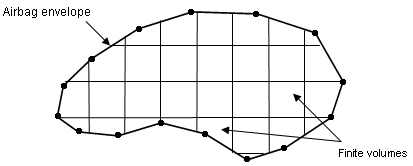
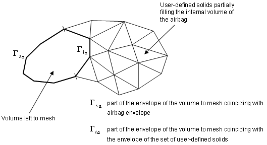
Some of these finite volumes can be entered by you through a group of solids, located inside the airbag and filling a part or the total internal volume. If there still exists a part of the internal volume which is not discretized by user-defined solids, an automatic meshing procedure produces the remaining volumes. This can be used for example to model a canister.

A finite volume consists in a set of triangular facets. Their vertices do not necessarily coincide with the nodes of the airbag. The airbag envelope can be modeled with 4-node or 3-node membranes; however, 3 nodes are recommended.

monvol_airbag-env


monvol_airbag2

6.Venting through vent holes:

If Iform = 1, venting velocity is computed from Bernoulli equation using local pressure in the airbag.

The exit velocity is given by:

The mass out flow rate is given by:

If Iform = 2, venting velocity is computed from the Chemkin equation.

If Iform = 3, venting velocity is equal to the component of the local fluid velocity normal to vent hole surface. Local density and energy are used to compute outgoing mass and energy through the hole.

7.When there is no sensor which activates gas injection, the vent holes and porosity becomes active, if time T becomes greater than the Tstart, or if the pressure P exceeds Pdef value longer than the time given in .
8.When at least one of the injectors is activated by the sensor, then activation of venting and porosity options is controlled by Ittf.

Tinj is the time of the first injector to be activated by the sensor.

Ittf = 0


Venting, Porosity

Activation

When longer than the time , or

Deactivation

Tstop

Time dependent functions

No shift

Ittf = 3


Venting, Porosity

Activation

When and longer than the time , or

Deactivation

Time dependent functions

Shifted by

All other related curves are active when the corresponding venting, porosity or communication option is active.

The variety of Ittf values comes from historical reasons. Values Ittf=1 and 2 are obsolete and should not be used. Usual values are Ittf=0 (no shift) or Ittf=3 (all relative options are shifted by Tinj).

9.If surf_IDv ≠ 0 (surf_IDv is defined)

where, A is the area of surface surf_IDv, A0 is the initial area of surface surf_IDv , and ft, fP and fA are functions of fct_IDt, fct_IDP and fct_IDA

10.In the case of activated venting closure the vent holes surface is computed as follows:


with impacted surface:

and non-impacted surface:

Image12

where for each element e of the vent holes surf_IDv, nc(e) means the number of impacted nodes among the n(e) nodes defining the element.

A0 is the initial area of surface surf_IDv

ft, fP and fA are functions of fct_IDt, fct_IDP and fct_IDA

ft’, fP’ and fA are functions of fct_IDt’, fct_IDP’ and fct_IDA’

11.If surf_IDv = 0 (surf_IDv is not defined) RADIOSS ends with a Starter error.
12.Functions fct_IDt and fct_IDP are equal to 1, if they are not specified (null identifier).
13.Function fct_IDA is assumed to be equal to 1, if it is not specified.
14.To account for contact blockage of vent holes and porous surfaces, flag IBAG must be set to 1 in the correspondent interfaces (Line 3 of interface TYPE7 or TYPE23). If not, the nodes impacted into the interface are not considered as impacted nodes in the previous formula for Aimpacted and Anon_impacted .
15.Leakage by porosity formulations, the mass flow rate flowing out is computed as:
Iformps = 1 (Isentropic - Wang Nefske)
Iformps = 2 where v is the outflow gas velocity (Chemkin)
Iformps = 3 (Graefe)

The effective venting area Aeff is computed according to the input in the /LEAK/MAT input for fabric materials of TYPE19 or TYPE58.

16.If leakage blockage is activated, Iblockage=1, the effective venting area is modified as follows:

is non-impact surface (Comment 10)

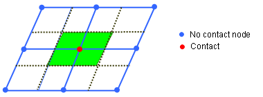
The blockage will be active only if flag IBAG is set to 1 in the concerned contact interfaces (line 3 of interface TYPE7 and TYPE23).

17.Automatic finite volume meshing parameters.

monvol_finite_vol

18.The finite volumes are generated in two steps.
The first step generates vertices lying exclusively on the envelope of the airbag. You can update the finite volume along with the deformation of the envelope and correspond to the following procedure (displayed in 2D for purpose of clarity):

monvol_step1

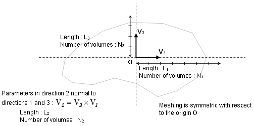
This procedure requires the input of the direction V3, named cutting direction, and of the direction V1. A second direction V2 in the plan normal to the cutting direction will be computed. In order to position the finite volumes and to determine the cutting width in both direction V1 and V2, an origin O must be provided as well as a length Li, counted both positively and negatively from the origin, and a number of steps Ni. The cutting width is then given by:

It is required that the box drawn in the horizontal plane (normal to V3 ) by the origin O and the length Li, counted both positively and negatively from O, includes the bounding-box of the envelope of the volume to mesh projected in this plane. This is necessary to ensure that this volume in entirely divided into finite volumes.

The second step performs horizontal cutting of the finite volumes, and may be useless in many cases of tightly folded airbags. It is required especially when injection is made in a canister filled by the injected gas before unfolding the airbag.

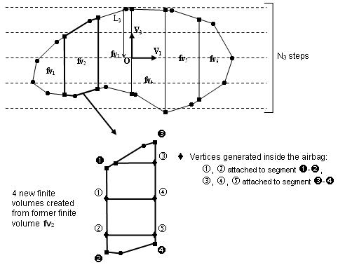
This second step may generate vertices located inside the airbag. In order for them to be moved along with the inflation of the airbag, each is attached to a vertical segment (parallel to direction V3) between two vertices lying on the envelope of the airbag (see figure below). The local coordinates of the vertex within its reference segment remain constant throughout the inflation process.

monvol_fvmbag

The horizontal cutting width is given by:

It is not necessary that the segment given in the V3 direction by the origin O and length L3, counted both positively and negatively, includes the bounding-box of the envelope of the volume to mesh projection on the V3 direction, since at the second step only existing finite volumes are cut.

19.Actual vector V1 used for automatic meshing is obtained after orthogonalization of the input vector with respect to vector V3.
20.When a finite volume fails during the inflation process of the airbag (volume becoming negative, internal mass or energy becoming negative), it is merged to one of its neighbors so that the calculation can continue. Two merging approaches are used:
Global merging: a finite volume is merged if its volume becomes less than a certain factor multiplying the mean volume of all the finite volumes. The flag Igmerg determines if the mean volume to use is the current mean volume (Igmerg =1) or the initial mean (Igmerg =2). The factor giving the minimum volume from the mean volume is Cgmerg.
Neighborhood merging: a finite volume is merged if its volume becomes less than a certain factor multiplying the mean volume of its neighbors. The factor giving the minimum volume from the mean volume is Cnmerg.
21.In the case of both Cgmerg and Cnmerg are not equal to 0, means both merging approach will be used simultaneously. In case of a strong shock, it is recommended to set qa = 1.1 and qb = 0.05.
22.When two layers of fabric are physically in contact, there should be no possible flow between finite volumes, which is numerically not the case because of interface gap. Hmin represents a minimum height for the triangular facets below which the facet is impermeable. Its value should be close to the gap of the self-impacting interface of the airbag.
23.Nlayer, Nfacmax, and Nppmax are memory parameters that help the finite volume creation process. Changing their value cannot cause the calculation to stop. Increasing the leads to a higher amount of memory and a smaller computation time for automatic meshing.
24.During the finite volume creation process, plane polygons are first created, which are then assembled into closed polyhedra and decomposed into triangular facets. Nppmax is the maximum number of vertices of these polygons.
25.Automatic finite volume meshing based on reference geometry can be activated with flag Iref=1. It only works with a reference geometry based on /REFSTA and /XREF. The flag is not supported when disjointed reference geometry /EREF is used. Note that for Iref=1, the frame definition for automatic meshing should refer to non-folded reference geometry.
26.Surface surf_IDin is used to take internal surfaces or baffles into account as obstacles to the gas flow inside the monitored volume. Internal surfaces are taken into account in FVM only if the monitored volume is meshed automatically with polyhedron or if it is filled with solid elements, like TETRA4 (possibly HEXA and PENTA) with nodes coinciding with the monitored volume external and internal surface nodes (these solids must be declared in grbrick_ID). A porosity ranging from 0: no porosity up to 1: full porosity (vent) can be applied to internal surface fabrics only if their material model is LAW19 or LAW58. Injector surface can also be defined on an internal surface in which case the gas flow direction is opposite to the internal surface normal orientation.
27.The lost heat flow is given by:

28.If an element of a vent hole surface (surf_IDv) belongs to an injector (surf_IDinj) it will be ignored from the vent hole. A constant correction factor f  computed at time t=0 is applied to the total vent hole surface:

29.If an element of a porous surface also belongs to an injector (surf_IDinj), it will be ignored from the porous surface.

See Also:

FVM Airbag Guidelines