Field
|
Contents
|
SI Unit Example
|
monvol_ID
|
Monitored volume identifier
(Integer, maximum 10 digits)
|
|
unit_ID
|
Optional unit identifier
(Integer, maximum 10 digits)
|
|
monvol_title
|
Monitored volume title
(Character, maximum 100 characters)
|
|
surf_IDex
|
External surface identifier (see Comment 1)
(Integer)
|
|
Ascalet
|
Abscissa scale factor for time based functions
Default = 1.0 (Real)
|

|
AscaleP
|
Abscissa scale factor for pressure based functions
Default = 1.0 (Real)
|

|
AscaleS
|
Abscissa scale factor for area based functions
Default = 1.0 (Real)
|

|
AscaleA
|
Abscissa scale factor for angle based functions
Default = 1.0 (Real)
|

|
AscaleD
|
Abscissa scale factor for distance based functions
Default = 1.0 (Real)
|

|
Pext
|
External pressure
(Real)
|
|
T0
|
Initial temperature
Default = 295 (Real)
|

|
Iequi
|
Initial thermodynamic equilibrium flag
(Integer)
= 0: the mass of gas initially filling the airbag is determined with respect to the volume at time zero.
= 1: the mass of gas initially filling the airbag is determined with respect to the volume at beginning of jetting.
|
|
Ittf
|
Venting time shift flag. Active only when injection sensor is specified.
= 0 or 1: time dependent porosity curves are not shifted by injection sensor activation time. Tvent and Tstop are ignored.
= 2: time dependent porosity curves are shifted by Tinj (Tinj defined as the time of the first injector to be activated by the sensor). Tvent and Tstop are ignored.
= 3: time dependent porosity curves are shifted by by Tinj + Tstart. Venting is stopped at Tinj + Tstop, when Tstop is specified.
|
|
 i i
|
Ratio of specific heats at initial temperature (see Comment 5)
(Real)
|
|
cpai
|
cpa coefficient in the relation cpi(T)
(Real)
|

|
cpbi
|
cpb coefficient in the relation cpi(T)
(Real)
|

|
cpci
|
cpc coefficient in the relation cpi(T)
(Real)
|

|
Njet
|
Number of injectors
(Integer)
|
|
|
Ratio of specific heats

(Real)
|
|
cpa
|
cpa coefficient in the relation cp(T)
(Real)
|
|
cpb
|
cpb coefficient in the relation cp(T)
(Real)
|
|
cpc
|
cpc coefficient in the relation cp(T)
(Real)
|
|
fct_IDmas
|
Mass of injected gas versus time identifier
(Integer)
|
|
Iflow
|
Mass versus time function input type flag
(Integer)
= 0: mass is input
= 1: mass flow is input
|
|
Fscalemas
|
Scale factor on mass function
Default = 1.0 (Real)
|
 or or 
|
fct_IDT
|
Temperature of injected gas versus time identifier
(Integer)
|
|
FscaleT
|
Temperature scale factor
Default = 1.0 (Real)
|
|
sens_ID
|
Sensor identifier to start injections
(Integer)
|
|
Isjet
|
Injector surface identifier (must be different for each injectors)
(Integer)
|
|
fct_IDvel
|
Injected gas velocity identifier
(Integer)
|
|
Fscalevel
|
Injected gas scale factor
Default = 1.0 (Real)
|

|
Nvent
|
Number of vent holes
(Integer)
|
|
surf_IDv
|
Vent holes membrane surface (Real) or porous surface identifier
(Integer)
|
|
Avent
|
if surf_IDv ≠ 0: scale factor on surface
Default = 1.0
if surf_IDv = 0: surface of vent holes
Default = 0.0
(Real)
|
, if surf_IDV = 0
|
Bvent
|
if surf_IDv ≠ 0: scale factor on impacted surface
Default = 1.0
if surf_IDv = 0: Bvent is reset to 0
Default = 0.0
(Real)
|
, if surf_IDV = 0
|
Itvent
|
Venting formulation (see Comment 7)
Default = 2 (Integer)
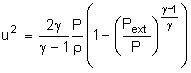
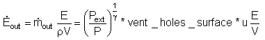
= 1: venting velocity is equal to the component of the local fluid velocity normal to vent hole surface. Local density and energy are used to compute outgoing mass and energy through the hole.
= 2: venting velocity is computed from Bernoulli equation using local pressure in the airbag. Local density and energy are used to compute outgoing mass and energy.
= 3: venting velocity is computed from Chemkin equation
|
|
Tvent
|
Start time for venting
Default = 0.0 (Real)
|
|
 Pdef Pdef
|
Pressure difference to open vent hole membrane (Pdef = Pdef - Pext)
(Real)
|
|
tPdef
|
Minimum duration pressure exceeds Pdef to open vent hole membrane
(Real)
|
|
fct_IDV
|
Outflow velocity function identifier
(Integer)
|
|
FscaleV
|
Scale factor on fct_IDV
Default = 1.0 (Real)
|
|
IdtPdef
|
Time delay flag when Pdef is reached:
= 0: pressure should be over Pdef during a tPdef cumulative time to activate venting
= 1: venting is activated tPdef after Pdef is reached
|
|
fct_IDt
|
Porosity vs time function identifier
(Integer)
|
|
fct_IDP
|
Porosity vs pressure function identifier
(Integer)
|
|
fct_IDA
|
Porosity vs area function identifier
(Integer)
|
|
Fscalet
|
Scale factor for fct_IDt
Default = 1.0 (Real)
|
|
FscaleP
|
Scale factor for fct_IDP
Default = 1.0 (Real)
|
|
FscaleA
|
Scale factor for fct_IDA
Default = 1.0 (Real)
|
|
fct_IDt’
|
Porosity vs time when contact function identifier
(Integer)
|
|
fct_IDP’
|
Porosity vs pressure when contact function identifier
(Integer)
|
|
fct_IDA’
|
Porosity vs impacted surface function identifier
(Integer)
|
|
Fscalet'
|
Scale factor for fct_IDt'
Default = 1.0 (Real)
|
|
FscaleP'
|
Scale factor for fct_IDP'
Default = 1.0 (Real)
|
|
FscaleA'
|
Scale factor for fct_IDA'
Default = 1.0 (Real)
|
|
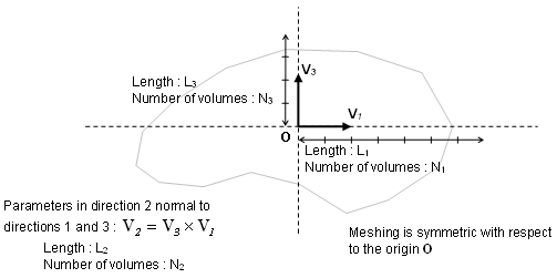
Vx3
|
X component of vector V3 (in global frame)
(Real)
|
|
Vy3
|
Y component of vector V3 (in global frame)
(Real)
|
|
Vz3
|
Z component of vector V3 (in global frame)
(Real)
|
|
Vx1
|
X component of vector V1 (in global frame)
(Real)
|
|
Vy1
|
Y component of vector V1 (in global frame)
(Real)
|
|
Vz1
|
Z component of vector V1 (in global frame)
(Real)
|
|
X0
|
X coordinate of local origin O (in global frame)
(Real)
|
|
Y0
|
Y coordinate of local origin O (in global frame)
(Real)
|
|
Z0
|
Z coordinate of local origin O (in global frame)
(Real)
|
|
L1
|
Length L1
(Real)
|
|
L2
|
Length L2
(Real)
|
|
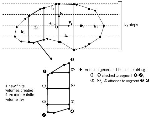
L3
|
Length L3
(Real)
|
|
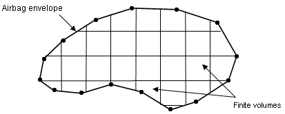
Nb1
|
Number of finite volumes in direction 1
Default = 1 (Integer)
|
|
Nb2
|
Number of finite volumes in direction 2
Default = 1 (Integer)
|
|
Nb3
|
Number of finite volumes in direction 3
Default = 1 (Integer)
|
|
grbric_ID
|
User-defined solid group identifier
(Integer)
|
|
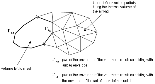
surf_IDin
|
Internal surfaces identifier (see Comment 25)
(Integer)
|
|
Iref
|
Flag for applying the automated FVM mesh on the reference geometry (see Comment 24)
= 0: no
= 1: yes
Default = 0 (Integer)
|
|
Igmerg
|
Global merging formulation flag (see Comment 19)
Default = 1 (Integer)
|
|
Cgmerg
|
Factor for global merging (see Comment 19)
Default = 0.02 (Real)
|
|
Cnmerg
|
Factor for neighborhood merging (see Comment 19)
(Real)
|
|
Ptole
|
Tolerance for finite volume identification
Default = 10-5 (Real)
|
|
qa
|
Quadratic bulk viscosity
Default = 0.0 (Real)
|
|
qb
|
Linear bulk viscosity
Default = 0.0 (Real)
|
|
Hmin
|
Minimum height for triangle permeability (see Comment 21)
(Real)
|
|
Ilvout
|
Output level: 0 or 1
Default = 0 (Integer)
|
|
Nlayer
|
Estimated number of layers in airbag folding along direction V3 (see Comment 22)
Default = 10 (Integer)
|
|
Nfacmax
|
Estimated maximum number of airbag segments concerned by a finite volume in the first automatic meshing step.
Default = 20 (Integer)
|
|
Nppmax
|
Estimated maximum number of vertices of a polygon
Default = 20 (Integer)
|
|
Ifvani
|
Write finite volumes in RADIOSS Starter Animation A000 File flag
(Integer)
= 0: no
= 1: yes
|
|