| 1. | surf_IDex must be defined using segments associated with 4-nodes or 3-nodes shell elements (possibly void elements). |
| 2. | The volume must be closed and the normals must be oriented outwards. |
| 3. | Abscissa scale factors are used to transform abscissa units in airbag functions, for example: |
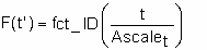
where, t is the time.
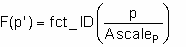
where, p is the pressure.
| 4. | The initial pressure is set to Pext. |
| 5. | The gas within each communicating chamber should have the same characteristics:  and cp. and cp. |
| 6. | Initial thermodynamic equilibrium is written at time zero (Iequi =0) or at beginning of jetting (Iequi =1), based on the following equation with respect to the volume at time zero, or the volume at beginning of jetting: |
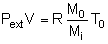
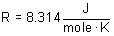
where, M0 is the mass of gas initially filling the airbag, Mi is the molar mass of the gas initially filling the airbag, and R is the gas constant depending on the units system.
| 7. | Ratio of specific heats at constant pressure per mass unit cpi of the gas initially filling the airbag is quadratic versus temperature: |
cpi(T) = cpa + cpbi * T + cpci * T2
| 8. | Gas constant at initial temperature i must be related to specific heat per mass unit at initial temperature and molar mass of the gas initially filling the airbag with respect to the following relation: |
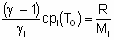
where, Mi is the molar mass of the gas initially filling the airbag and R is the gas constant depending on the units system.
| 9. | The characteristics of the gas initially filling the airbag must be defined (no default) and must be equal for each communicating airbag. |
| 10. | Ratio of specifics at constant pressure per mass unit cpi of the gas is quadratic with regard to the temperature: |
cp(T) = cpa + cpb * T + cpc * T2
| 11. | Gas constant at initial temperature must be related to specific heat per mass unit at initial temperature and molar mass of the with respect to the following relation: |
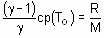
where, M is the molar mass of the gas and R is the gas constant depending on the units system.
| 12. | If jetting is used, an additional  Pjet pressure is applied to each element of the airbag: Pjet pressure is applied to each element of the airbag: |
Pjet = P(t) * P( ) * P( ) * P( ) * max ( ) * max ( * * ,0) ,0)
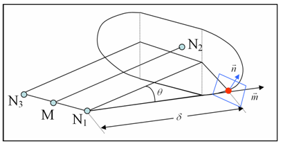
| 13. | With being the normalized vector between the projection of the center of the element upon segment (node_ID1 and node_ID3 ) and the center of the element; the angle between vectors MN2 and (in degrees), the distance between the center of the element and its projection upon segment (node_ID1 and node_ID3 ). |
The projection of a point upon segment (node_ID1 and node_ID3 ) is defined as the projection of the point in direction MN2 upon the line (node_ID1 and node_ID3 ) if it lies inside the segment (node_ID1 and node_ID3 ). If this is not the case, the projection of the point upon segment (node_ID1 and node_ID3 ) is defined as the closest node node_ID1 or node_ID3 (see following figure: dihedral shape of the jet).
with M between of N1 and N3
| 14. | If node_ID3 = 0, node_ID3 is set to node_ID1 and the dihedral shape is reduced to a conical shape. |
| 15. | Vent hole membrane is deflated if T > Tvent or if the pressure exceeds Pdef during more than tPCdef. |
| 16. | If fct_IDV = 0: isenthalpic outflow is assumed, else Chemkin model is used and outflow velocity is: |
 = FscaleV * fct_IDV (P - Pext ) = FscaleV * fct_IDV (P - Pext )
Venting or the expulsion of gas from the volume, is assumed to be isenthalpic.
The flow is also assumed to be unshocked, coming from a large reservoir and through a small orifice with effective surface area, A.
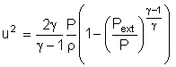
Conservation of enthalpy leads to velocity, u at the vent hole. The Bernouilli equation is then written as:
(monitored volume) 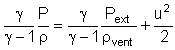 (vent hole) (vent hole)
Applying the adiabatic conditions:
(monitored volume)  (vent hole) (vent hole)
Where, P is the pressure of gas into the airbag and  is the density of gas into the airbag. is the density of gas into the airbag.
Therefore, the exit velocity is given by:
For supersonic flows the outlet velocity is determined as described in 10.4.4.1 of the Theory Manual.
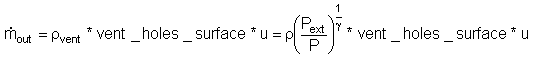
The mass out flow rate is given by:
The energy flow rate is given by:
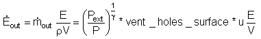
Where, V is the airbag volume and E is the internal energy of gas into the airbag.

Where, is the density of the gas within the airbag.
| 17. | If surf_IDv ≠ 0 (surf_IDv is defined). |
vent_holes_surface = Avent * fct_IDA(A) * fct_IDt(t) * fct_IDP (P - Pext)
Where, A is the Area of surface surf_ID.
| 18. | If surf_IDv = 0 (surf_IDv is not defined). |
vent_holes_surface = Avent * fct_IDt(t) * fct_IDP (P - Pext )
| 19. | Functions fct_IDt and fct_IDP are assumed to be equal to 1, if they are not specified (null identifier). |
| 20. | Function fct_IDA is assumed as the fct_IDA(A) = A, if it is not specified. |
| 21. | In order to use porosity during contact, flag IBAG must be set to 1 in the interfaces concerned (Line 3 of interface Type 5 and Type 7). If not, the nodes impacted into the interface are not considered as impacted nodes in the previous formula for Aimpacted and Anon_impacted. |
| 20. | Vent holes surface is computed as follows: |
If surf_IDv = 0 (surf_IDv is not defined).
vent_holes_surface = Avent * fct_IDA(A) * fct_IDt(t) * fct_IDP (P - Pext)
| 23. | If surf_IDv ≠ 0 (surf_IDv is defined). |
vent_holes_surface = Avent * Anon_impacted * fct_IDt(Anon_impacted/A0) * fct_IDP (P - Pext)
+ Bvent * Aimpacted * fct_IDt’(Aimpacted/A0) * fct_IDP’ (P - Pext)
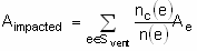
with impacted surface:
and non-impacted surface:
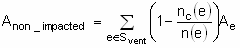
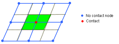
where for each element e of the vent holes surf_IDv, nc(e) means the number of impacted nodes among the n(e) nodes defining the element.
(see following figure: from nodes contact to impacted/non-impacted surface)
| 24. | Functions fct_IDt' and fct_IDP' are assumed to be equal to 1, if they are not specified (null identifier). |
| 25. | Function fct_IDA' is assumed as the fct_IDA'(A) = A, if it is not specified. |
| 26. | All communicating airbags bag_ID should be type COMMU monitored volumes. |
| 27. | Only the communication from the monitored volume monvol_ID to airbag bag_ID is considered (outwards communication). |
| 28. | When defining venting, there are some limitations concerning the definition of airbag surface and surface venting: |
| • | The airbag external surface should be built only from shells and 3-nodes shell elements. |
| • | The airbag external surface can not be defined with option /SURF/SEG (nor with option /SURF/SURF if a sub-surface is defined with option /SURF/SEG). |
| • | Same restriction applies to vent hole surface. |
| • | Shells and 3-nodes shell elements included in vent hole surface have to be included also in external surface. |
| • | Shells and 3-nodes shell elements included in communicating surface have to also be included in external surface. |
| 29. | Communication surface is open if T > Tvent or if the pressure exceeds PCdef during more than tPCdef. |
|


