|
»Click here to display Table of Contents«
|

Example 5 - Beam Frame |

|

|

|

|
|
Example 5 - Beam Frame |
|
|
|

|
|
»Click here to display Table of Contents«
|
Example 5 - Beam Frame |
|
|
|
|
|
Example 5 - Beam Frame |
|
|
|
|
A beam frame with clamped extremities receives an impact at its mid-point from a pointed mass having initial velocity. The material is subjected to the elasto-plastic law of Johnson-Cook. The model is meshed with beam elements. An infinite rigid wall with only one slave node, including the impacted node, is subjected to the initial velocity. This example is considered a dynamic problem and the explicit solver is used.
The explicit approach leads to finding a quasi-static equilibrium of the structure after impact.
TitleBeam-frame |
|
||||||||
Number5.1 |
|||||||||
Brief DescriptionA beam frame receives an impact from a mass having initial velocity. |
|||||||||
Keywords
|
|||||||||
RADIOSS Options
|
|||||||||
Input FileBeam_frame: <install_directory>/demos/hwsolvers/radioss/05_Beam-frame/FRAME* |
|||||||||
Technical / Theoretical LevelBeginner |
|||||||||
The purpose of this example is to perform a static analysis using beam elements.
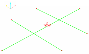
A pointed mass (3 kg) makes an impact at point O of a beam frame (see Fig 1 for the geometry) using a speed of 10 ms-1 in the Z direction. The beams are made of steel and each beam section is square-shaped (each side being 6 mm long).
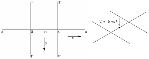
Fig 1: Geometry of the frame.
Dimensions are: AB = BC = CD = BE = BF = E’C = CF’ = 90 mm.
Points A, D, E, F, E’, and F’ are fixed.
The beams have the following properties:
| • | Cross section: 36 mm2 |
| • | Moments of inertia in Y and Z: 108 mm4 |
| • | Moments of inertia in X : 216 mm4 |
The steel material used has the following properties:
| • | Density: 0.0078 g/mm3 |
| • | Young’s modulus: 200 000 MPa |
| • | Poisson’s ratio: 0.3 |
| • | Yield stress: 320 MPa |
| • | Hardening parameter: 134.65 MPa |
| • | Hardening exponent: 1.0 |
All other coefficients are set to default values. Plasticity is taken into account using Law 2 without failure.
The mesh is a regular beam mesh, each beam being 9 mm long (total = 70 beams).
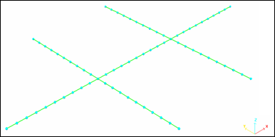
Fig 2: Mesh of the frame showing the position of the nodes.
The impacting mass is simulated using a sliding rigid plane wall (/RWALL) having an initial velocity of 10 ms-1 and a mass of 3000 g. Only one slave node exists: the node O to simulate a point impact.
Points A, F, F', D, E and E' are fully fixed.
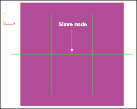
| Fig 3: Boundary conditions | Fig 4: Rigid wall type infinite plane |
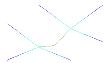
The main results refer to the time history of points B and O with regard to displacements and velocities.
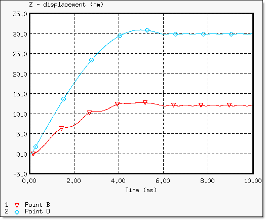
Fig 5: Displacements of points B and O.
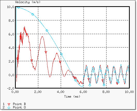
Fig 6: Velocity of points B and O (stabilization).
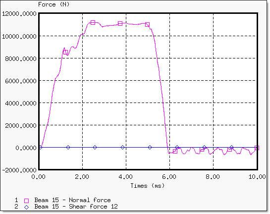
Fig 7: Normal and shear force on beam element 15 (near to point O).
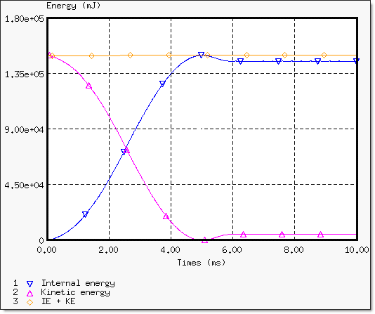
Fig 8: Energy assessment (stability reached at in 6 ms).
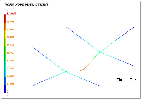
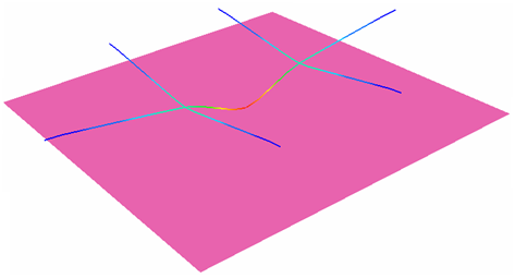
Fig 9: Node displacement (max. = 30.96 mm).
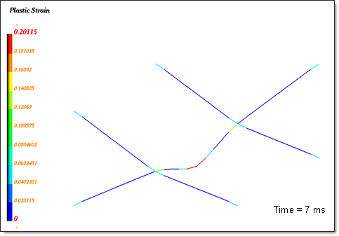
Fig 10: Plastic strain (max. = 20.1%).