Summary
Thermal analysis, like heat exchange (between two contact surfaces, between heat object and surrounding atmosphere though convection or radiation, inside the object through conduction), deformation is due to thermal expansion or heat generated, due to friction can be simulated in RADIOSS. In this example heat exchange is discussed between a moving heat source and one plate, due to contact and also between plate and atmosphere (water) through convective flux.
Title
Thermal Analysis – Heat Exchange
|
|
Number
53.1
|
Brief Description
A heat source moved on one plate. Heat exchanged between a heat source and a plate through contact, also between a plate and the atmosphere (water) through convective flux.
|
Keywords
|
RADIOSS Options
| • | Boundary conditions (/BCS) |
|
Input File
<install_directory>/demos/hwsolvers/radioss/53_thermal_analysis/Heat_exchange/*
|
Technical / Theoretical Level
Advanced
|
Overview
Physical Problem Description
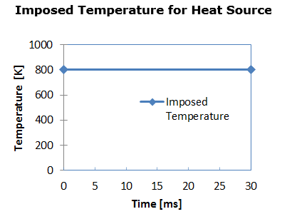
A heat source with a constant temperature of 800K is moved under imposed displacement on one plate with an initial temperature of 298K. The dimension of the heat source is 5mm x 5mm and the plate is 100mm x 100mm.
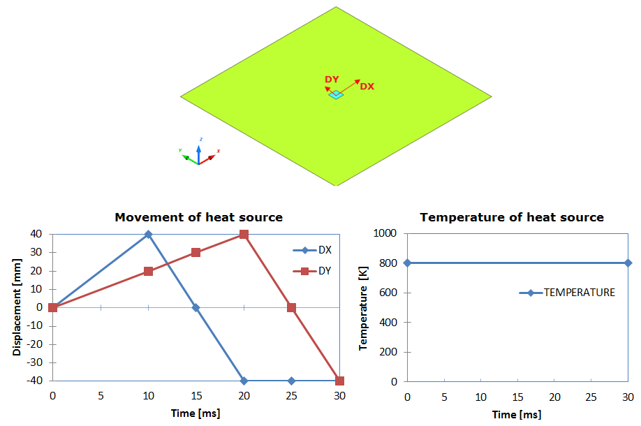
Fig 1: Problem description.
Units: mm, ms, g, N, and MPa
/MAT/LAW2 and /HEAT/MAT are used to describe the aluminum heat source and plate, with the following characteristics:
| • | Initial density: 2.8 x 10⁻³ |
| • | Young modulus: 70000 [MPa] |
| • | Hardening parameter: 450 [MPa] |
| • | Room temperature: 298 [K] |
| • | Specific heat  : 2.51 : 2.51 |
| • | Initial temperature for heat source: 800 [K] and for plate: 398 [K] |
| • | Thermal conductivity coefficient AS: 0.23  |
Analysis, Assumptions and Modeling Description
Modeling Methodology
/HEAT/MAT is an additional material law card used to describe the material thermal character. So the material ID in the material law in /MAT and in /HEAT/MAT must be the same. The thermal parameter defined in /HEAT/MAT will recover the same parameters which are defined in the material law.
Heat capacity provides heat and mass the ability to change the temperature. In engineering and science, it is recommended to use specific heat capacity, which is heat capacity divided by mass,  in SI unit. Heat capacity is
  for aluminum. Refer to Material Constants in the Theory Manual Appendices for more information on heat capacity of ordinary material.
For the thermal conductivity coefficient AS,  . Thermal conductivity
  for aluminum, and constant thermal conductivity. Set BS=0. Since thermal conductivity k=AS+BS*T, then k=AS, in this case.
With /IMPTEMP, imposed temperature will be set on a group of nodes. The source constant temperature is defined for heat source.
Use /CONVEC to describe the heat exchange between a structural component and its surrounding atmosphere (infinite room).
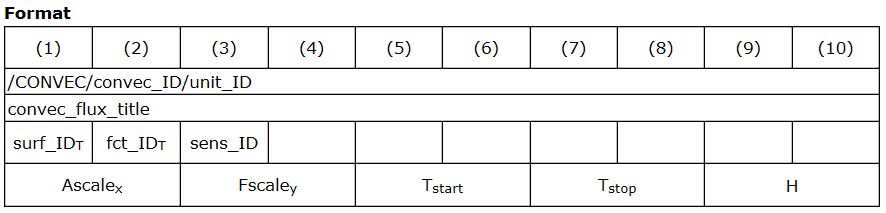
The surrounding atmosphere is water with a constant temperature of 298K, which is described in function, fct_IDT (Figure 3).
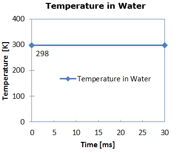
Fig 3: Temperature in water.
Where, H is the heat transfer coefficient between structural component and its surrounding infinite room with unit  . In general, the convective heat transfer coefficient for water (free convection) is about 20 - 100
  and water (forced convection) is about 50 - 10000
  . Forced convection in water is
  .
.
In /INTER/TYPE7, heat exchange between the heat source and plate during the contact, is defined Ithe=1 to activated heat transfer between master and slave.
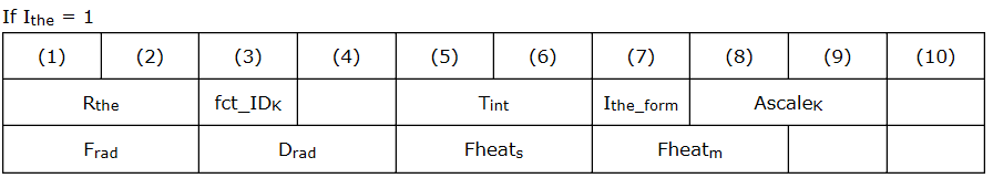
Ithe_form set to 1 for heat exchange between all pieces in contact.
There are two ways to define heat exchange between contact parts.
| 1. | Define constant heat exchange coefficient using Kthe ( in SI unit). In this case, fct_IDK = 0. in SI unit). In this case, fct_IDK = 0. |
| 2. | If fct_IDK ≠ 0, the heat exchange coefficient is the function of contact pressure using this curve and Kthe is the scale factor. |

Interfacial heat transfer coefficient, K described conductive heat flux through a unit area of a plate with particular thickness. The range of this heat transfer coefficient can be very large, which will affect the accuracy of simulation. To get a more accurate result, experimental test are required.
Set Fheats and Fheatm to zero, to not consider heat friction.
Simulation Results and Conclusions
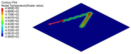
The following figure shows nodal temperature at time 10[ms], 20[ms] and 30[ms]. Part of heat transferred to plate through contact. Therefore, the temperature under the trace increased. The temperature on the plate decreased during the time, due to the convection with water.
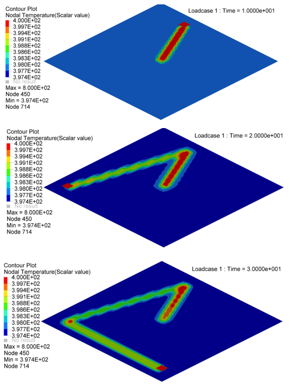
Fig 4: Nodal temperature in plate at time=10[ms], 20[ms] and 30[ms].
Below the nodal temperature on Nodal N641, N1034, N958 and N1708 are illustrated.
| 1. | Nodal N641 is not under trace. The temperature changed, only due to convection with water. |
| 2. | Nodal N1034, N958 and N1708 are under trace. At first the temperature decreased before the heat source began, due to convection with water, and then increased, due to the heat exchange from the heat source through contact. Once the heat source is removed, the temperature decreased again, due to the heat conduction inside the material and convection with water. So the slope of the temperature decrease is much larger than N641 (only convection). |
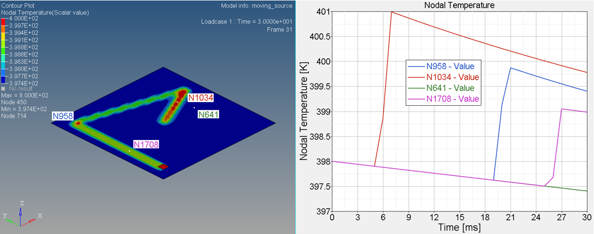
Fig 5: Temperature on Nodal N641, N1034, N958 and N1708


