|
»Click here to display Table of Contents«
|

Example 23 - Brake |

|

|

|

|
|
Example 23 - Brake |
|
|
|

|
|
»Click here to display Table of Contents«
|
Example 23 - Brake |
|
|
|
|
|
Example 23 - Brake |
|
|
|
|
A frictional mechanism is studied, which consists of a brake system, defined by a disk pinched between two pads. The main aspects of the model are the initial rotary motion of the disk and the interface definition, between the disk and the pads. Carefully watch the accuracy of the simulation results compared to the analytical solution.
TitleBrake |
|
||||||||||||||
Number23.1 |
|||||||||||||||
Brief DescriptionA brake system is simulated using a finite Lagrangian mesh element. |
|||||||||||||||
Keywords
|
|||||||||||||||
RADIOSS Options
|
|||||||||||||||
Input FileLagrangian formulation: <install_directory>/demos/hwsolvers/radioss/23_Brake/Lagrangian_formulation/BRAKE2* |
|||||||||||||||
Technical / Theoretical LevelAdvanced |
|||||||||||||||
The purpose of this example is to highlight the capacity of RADIOSS to simulate frictional mechanisms. The braking system retained consists of a disk pinched in between two pads.
A disk with a hole in the center rotates at ![]() 0 = 120 rad/s around its axis. It is subjected to frictional contact using two small brake pads, placed on two faces.
0 = 120 rad/s around its axis. It is subjected to frictional contact using two small brake pads, placed on two faces.
| Description of the disk: | Radius = 100 mm |
Width = 50 mm
Thickness = 5 mm
Mass = 1 kg
Inertia = 0.57x10⁻² kg/m2 (about its free rotation axis).
| Description of the pads: | Length = 65 mm |
Width = 28 mm
Thickness = 5 mm
A constant P = 300N pressure is applied on the back of each pad to push them against the disk. A Coulomb friction coefficient is assumed as being 0.15.
Units: m, s, kg
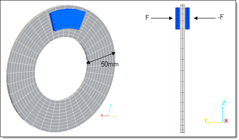
Fig 1: Geometry of the problem.
The material used for the disk follows an isotropic elasto-plastic law (/MAT/LAW2) using the Johnson-Cook plasticity model, with the following characteristics:
| • | Initial density: 7800 Kg/m3 |
| • | Young modulus: 210000 MPa |
| • | Poisson ratio: 0.3 |
| • | Yield stress: 206 MPa |
| • | Hardening parameter: 450 MPa |
| • | Hardening exponent: 0.5 |
| • | Maximum stress: 340 MPa |
The material used for the pads follows a linear elastic law, with the following characteristics:
| • | Initial density: 7300 Kg/m3 |
| • | Young modulus: 160000 MPa |
| • | Poisson ratio: 0.3 |
The two parts are modeled using a regular mesh having 720 BRICK elements for the disk and 80 such elements for the pads. The HEPH formulation is used to describe the BRICK elements.
Two steps are necessary to compute the model: First, an initial velocity 0.03ms is applied to the disk. In the second step, pressure is applied to the pads to push them onto the disk.
| • | Rigid bodies: |
Two rigid bodies are created to put the disk into motion: the first (called RBODY1) contains all the nodes of the disk, except those in the disk’s internal periphery, which are contained in the second rigid body (called RBODY2). Both rigid bodies are activated in the first step of computation; however, RBODY1 is deactivated in the D02 file.
Two other rigid bodies are created to model the pads’ faces where concentrated loads are applied.
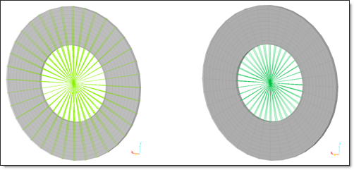
Fig 2: Rigid bodies on the disk (RBODY1 on the left and RBODY2 on the right).
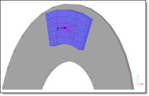
Fig 3: Rigid body on a pad.
| • | Boundary conditions: |
For the disk’s rigid bodies, all DOF, except the rotation around Y are fixed. For the pads’ rigid bodies, all DOF; except translation around Y are fixed.
| • | Load: |
Two concentrated opposite forces are applied to the rigid bodies’ master nodes for the pads.
| • | Initial velocity: |
An initial rotational velocity ![]() 0 = 120 rad/s is applied to the disk’s master nodes during the first computation phase.
0 = 120 rad/s is applied to the disk’s master nodes during the first computation phase.
The normal contact force between the pads and the disk is FN = 600N. Then the tangential friction force on the surface of the disk is obtained at FT = 0.15 x FN = 90N. The torque around the axis of the disk is T = r x FT = 7.1 Nm, with r = 0.0789 m, which corresponds to the orthogonal projection on a radial axis with regard to the distance between the center of the disk and the point of the pad where the load is applied. This leads to an angular deceleration of a = T / IR = 1246 rad/s2.
The necessary time to stop the disk can be computed as: t = ![]() 0 / a = 0.096 second.
0 / a = 0.096 second.
The simulation by RADIOSS using the explicit solver allows similar results to be obtained, as shown in the following diagrams. The following graph shows the time history for angular velocity. The disk stops at t = 0.095 s, which corresponds to the analytical solution.
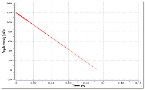
Fig 4: Angular velocity of the disk.
The following graph shows the total rotation of the disk, which rotates 5.65 rad before stopping.
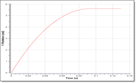
Fig 5: Total rotation of the disk.
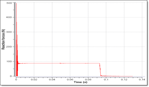
Fig 6: Reaction forces.
The reaction forces value in Fig 6 is about 90 N, which corresponds to the analytical value.
The total energy remains constant during computation. After braking, the kinetics energy decreases smoothly while the contact energy increases. There is no hourglass energy as a HEPH solid element is used.
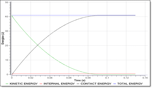
Fig 7: Energies.
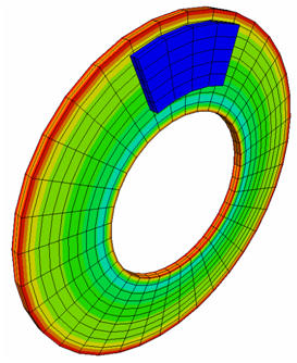
The following diagram presents the tangential contact forces for three consecutive moments.
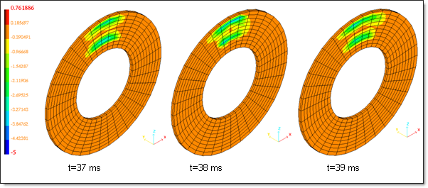
Fig 8: Variation of X-component of tangential contact forces.
The accuracy of the results obtained, using the simulation and corresponding to the analytical solution, proves that RADIOSS is able to simulate mechanisms, such as braking systems.