HyperWorks Solvers

/INTER/TYPE11

/INTER/TYPE11

Previous topic Next topic Expand/collapse all hidden text  

/INTER/TYPE11

Previous topic Next topic JavaScript is required for expanding text JavaScript is required for the print function  

Block Format Keyword

/INTER/TYPE11 - Interface Type 11 - Edge to Edge or Line to Line Interface

Description

This interface simulates impact between Edge to Edge or lines. A line can be a beam or truss element or a shell edge or spring elements. The interface properties are:

Impacts occur between a master and a slave line.
A slave line can impact on one or more master lines.
A line can belong to the master and the slave side. This allows self-impact.
This interface can be used in addition to interface TYPE7 to solve the edge to edge limitation of interface TYPE7.

Format

(1)

(2)

(3)

(4)

(5)

(6)

(7)

(8)

(9)

(10)

/INTER/TYPE11/inter_ID/unit_ID

inter_title

line_IDs

line_IDm

Istf

Ithe

Igap


Idel


Stmin

Stmax

%mesh_size

dtmin

Iform

sens_ID

Stfac

Fric

Gapmin

Tstart

Tstop

IBC


Inacti

VISS

VISF

Bumult

(Optional) Read this input, if Ithe > 0

(1)

(2)

(3)

(4)

(5)

(6)

(7)

(8)

(9)

(10)

Kthe

fct_IDK

AscaleK

Tint

Ithe_form


Frad

Drad


hmtoggle_plus1Flag Definition

Field

Contents

SI Unit Example

inter_ID

Interface identifier

(Integer, maximum 10 digits)


unit_ID

Optional unit identifier

(Integer, maximum 10 digits)


inter_title

Interface title

(Character, maximum 100 characters)


line_IDs

Slave line identifier

(Integer)


line_IDm

Master line identifier

(Integer)


Istf

Stiffness definition flag

Default = 5  (Integer)

= 0: default, set to the value defined in /DEFAULT/INTER/TYPE11

= 1: Stfac is a stiffness value

= 2, 3, 4 and 5 (default in case /DEFAULT/INTER/TYPE11 is not defined): Stfac is a stiffness scale factor and the interface stiffness is computed from both master and slave characteristics


Ithe

Heat transfer flag

(Integer)

= 0: no heat transfer

= 1: heat transfer is activated and the temperature of the master side is considered as constant (Tmaster = Tint).

= 2: heat transfer is activated and the temperature can be variable over the master surface and time.


Igap

Gap/element option flag

(Integer)

= 0: default, set to the value defined in /DEFAULT/INTER/TYPE11

= 1: gap varies accordingly to the characteristics of the impacted master line and the impacting slave node.

= 3: gap varies according to the characteristics of the impacted master line and the impacting slave node + gap is taken into account the size of the elements.

= 1000: gap is constant equal to Gapmin (default in case /DEFAULT/INTER/TYPE11 is not defined)


Stmin

Minimum stiffness (used only when Istf 1)

(Real)

Stmax

Maximum stiffness (used only when Istf 1)

Default = 1030  (Real)

%mesh_size

Percentage of mesh size (used only when Igap = 3)

Default = 0.4  (Real)


dtmin

Limiting nodal time step (Comment 12)

(Real)

Iform

Friction penalty formulation type (Comment 14)

(Integer)

= 0: default, set to the value defined in /DEFAULT/INTER/TYPE11

= 1: viscous (total) formulation (default in case /DEFAULT/INTER/TYPE11 is not defined)

= 2: stiffness (incremental) formulation


sens_ID

Sensor ID to Activate/Deactivate the interface (Comment 13)

(Integer)

If an ID sensor is defined, the activation/deactivation of interface is based on sensor and no more on Tstart, Tstop.


Idel

Node and segment deletion flag (Comment 4)

Default = 0 (Integer)

= 0: default, set to the value defined in /DEFAULT/INTER/TYPE11

= 1: when all the elements (4-node shells, 3-node shells, solids, beams, trusses, and springs) associated to one segment are deleted, the segment is removed from the interface. It is also removed in case of explicit deletion using RADIOSS Engine keyword /DEL in the Engine file.

Additionally, non-connected nodes are removed from the interface.

= 2: when an element (4-node shell, 3-node shell, solid, beam, truss, and springs) is deleted, the corresponding segment is removed from the interface. It is also removed in case of explicit deletion using RADIOSS Engine keyword /DEL in the Engine file.

Additionally, non-connected nodes are removed from the interface.

= 3: no deletion (default)

= -1: same as =1, except non-connected nodes are not removed from the slave side of the interface.

= -2: same as =2, except non-connected nodes are not removed from the slave side of the interface.

= 1000: no deletion (default in case /DEFAULT/INTER/TYPE11 is not defined)


Stfac

Interface stiffness (if Istf = 1)

Default = 1.0  (Real)

Stiffness scale factor for interface (if Istf ≠ 1);

Default = 0.0

(Real)

Fric

Coulomb friction

(Real)


Gapmin

Minimum gap for impact activation

(Real)

Tstart

Start time

(Real)

Tstop

Temporary deactivation time

(Real)

IBC

Deactivation flag of boundary conditions at impact

(Booleans)


Inacti

Deactivation stiffness flag (Comment 11)

(Integer)

= 0: default, set to the value defined in /DEFAULT/INTER/TYPE11

= 1: deactivation of stiffness on nodes

= 2: deactivation of stiffness on elements

= 3: change node coordinates to avoid initial penetrations

= 5: gap is variable with time and initial gap is computed as follows:

with the initial penetration

= 6: gap is variable with time but initial penetration is computed as follows (the node is slightly depenetrated):

= 1000: no action (default in case /DEFAULT/INTER/TYPE11 is not defined)


VISS

Critical damping coefficient on interface stiffness

Default set to 0.05  (Real)


VISF

Critical damping coefficient on interface friction

Default set to 1.0  (Real)


Bumult

Sorting factor (Comments 12 and 13)

Default set to 0.20  (Real)


Kthe

Heat exchange coefficient (if fct_IDK = 0) (Comment 15)

Default = 0.0

(Real)

Heat exchange scale factor (if fct_IDK ≠ 0) (Comment 15)

Default = 1.0

(Real)

fct_IDK

Heat exchange definition with contact pressure identifier

Default = 0  (Integer)


AscaleK

Abscissa scale factor on fct_IDK

Default = 1.0  (Real)

Tint

Interface temperature (Comment 15)

(Real)

Ithe_form

Heat contact formulation flag

(Integer)

= 0: exchange between constant temperature in the interface and shells (slave side)

= 1: heat exchange between pieces in contact


Frad

Radiation factor (Comment 17)

(Real)

Drad

Maximum distance for radiation computation (Comment 17)

(Real)

hmtoggle_plus1Flags for Deactivation of Boundary Conditions: IBC

(1)-1

(1)-2

(1)-3

(1)-4

(1)-5

(1)-6

(1)-7

(1)-8


IBCX

IBCY

IBCZ


Field

Contents

SI Unit Example

IBCX

Deactivation flag of X boundary condition at impact

(Boolean)

=0: free DOF

=1: fixed DOF


IBCY

Deactivation flag of Y boundary condition at impact

(Boolean)

=0: free DOF

=1: fixed DOF


IBCZ

Deactivation flag of Z boundary condition at impact

(Boolean)

=0: free DOF

=1: fixed DOF


hmtoggle_plus1Comments
1.A non-zero Gapmin value must be input in case of a line is a spring element.
2.In case of SPMD, each master segment defined by line_IDm must be associated to an element (possibly to a void element).
3.The user can define slave and master line with /LINE option.
4.Flag Idel =1 has a CPU cost higher than Idel =2.
5.A default value for Gapmin is computed as:

While,

: master surface gap

t: average thickness of the master elements for shell elements.

l: length of the smallest side of solid elements.

S: smallest cross section of the beam and truss elements.

: slave surface gap: computation identical to ; except that it is applied on slave side elements.

6.Variable gap
oIf Igap = 1000, gap is constant and is equal to Gapmin .
oIf Igap = 1, gap is variable and is computed for each impact as:

If Igap = 3, gap is variable and is computed for each impact as:

While,

gm: master element gap.

 with t: thickness of the master element for shell elements.

 with l: length of the smallest side of a solid element.

with S being the cross section of the truss and beam elements.

for spring elements.


gs: is computed the same way; except that it is applied on slave side elements.

gm_l : length of the smaller edge of element.

gs_l : length of the smaller edge of elements connected to the slave node.

The variable gap is always at least equal to Gapmin.

7.Contact stiffness There is no limitation value on the stiffness factor (but a value greater than 1.0 can reduce the initial time step). Contact stiffness computed as:

While,

Kn is computed from both master segment stiffness Km and slave segment stiffness Ks as follows if Istf ≠ 1:

Istf = 2,

Istf = 3,

Istf = 4,

Istf = 5,

Km is master segment stiffness and computed as follows:

when master segment lies on a shell or is shared by shell and solid:

when master segment lies on a solid:

Where,

S is the segment area,

V is the volume of the solid,

B is the Bulk Modulus

Ks is an equivalent nodal stiffness considered, and computed as:

when node is connected to a shell element:

when node is connected to solid element:


8. Deactivation of boundary condition is applied to nodes of surface 1.
9. Inacti = 3 may create initial energy if the node belongs to a spring element.

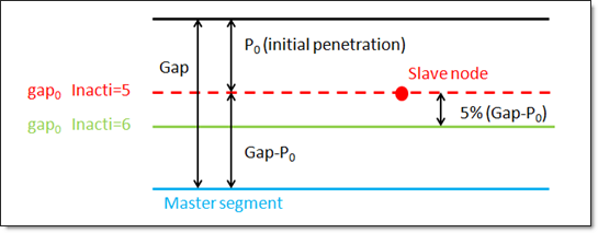
Inacti = 5 is recommended for airbag simulation deployment.

Inacti = 6 is recommended instead of Inacti = 5, in order to avoid high frequency effects into the interface.

Inacti_flag_6

10.The sorting factor Bumult is used to speed up the sorting algorithm.
11.The default value for Bumult is automatically increased to 0.30 for models which have more than 1.5 million nodes and to 0.40 for models with more than 2.5 million of nodes.
12.Slave segment is deactivated from the contact when the segment kinematic time step calculated for this contact becomes smaller than dmin.
13.When sens_ID is defined for activation/deactivation of the interface, Tstart and Tstop are not taken into account.
14.For friction formulation

Friction penalty formulation Iform

If Iform = 1, (default) viscous formulation, the friction forces are:

While an adhesion force is computed as follows:

with

If Iform = 2, stiffness formulation, the friction forces are:

While an adhesion force is computed as follows:

with

Where,

Vt is contact tangential velocity

Iform = 2 is recommended for implicit and low speed impact explicit analysis.

15. Heat exchange

By Ithe=1 (heat transfer activated) to consider heat exchange and heat friction in contact.

If Ithe_form = 0 then heat exchange is between shell and constant temperature contact Tint
If Ithe_form = 1 then heat exchange is between all contact pieces.

Tint is used only when Ithe_form=0. In this case. The temperature of master side assumed to be constant (equal to Tint). If Ithe_form=1 then Tint is not take into account. So the nodal temperature of master side will be considered.

If Ithe >1 needs the material of the slave side to be a thermal material using finite element formulation for heat transfer (see /HEAT/MAT).

Heat exchange coefficient

If fct_IDK = 0, then Kthe is heat exchange coefficient. And heat exchange depends only on heat exchange surface.
If fct_IDK ≠ 0, Kthe is a scale factor. And heat exchange depends on contact pressure:

While fK is function of fct_IDK.

16.Thermal conduction is computed when the slave node falls into the Gap
17. Radiation

Radiation is considered in contact if and the distance, d, of the slave node to the master segment is:

While Drad is the Maximum distance for radiation computation. The default value for Drad is computed as the maximum of:

upper value of the Gap (at time 0) among all nodes
smallest side length of slave element

It is recommended not to set the value too high for Drad, which may reduce the performance of RADIOSS Engine. The heat exchange is computed only from master to slave.

A radiant heat transfer conductance is computed as:

with

Where, is the Stefan Boltzman constant, is the emissivity of slave surface, and is the emissivity of master surface.

See Also:

Interface TYPE11 in User's Guide

Penalty Method in User's Guide

Interface TYPE11 in FAQ

Example 12 - Jumping Bicycle

Example 17 - Box Beam