Definition
Interface type 7 is a general purpose interface and can simulate all types of impact between a set of nodes and a master surface. Contrary to interface types 3 and 5, interface type 7 is non-oriented and slave nodes can belong to the master surface. Therefore, this interface can simulate self-impact, especially buckling during a high speed crash.
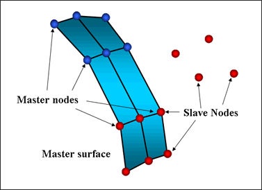
Fig. 5.10: Interface type 7
Interface type 7 solves all problems and limitations encountered with interface types 3 and 5. The search for the closest segment is done via a direct search algorithm; therefore, there are no search limitations and all possible contacts are found. The energy jumps induced by a node impacting from the shell edges are removed by the use of a cylindrical gap around the edges.
Finally, the main advantage of interface type 7 is that the stiffness is not constant and increases with penetration preventing the node from going through the shell mid-surface. This solves many bad contact treatments (common when using either interface type 3 or 5).
The gap used in interface type 7 is rather different than those of the previous interfaces. The gap used is on both sides of the shell mid-surface, and a cylindrical gap is added around the edges (Fig. 5.11).
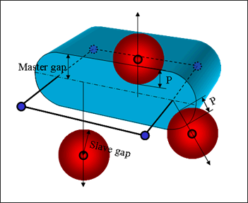
Fig. 5.11: Gap in Interface type 7
The cylindrical gap allows getting rid of energy jumps, node impacting from the edges follow the same path during the penetration and the depenetration. Moreover such a gap keeps the reaction force smooth during sliding between segments.
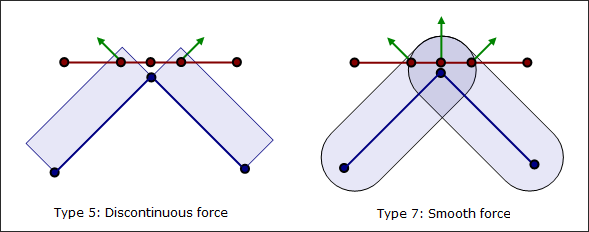
Fig. 5.12: Sliding between segments
Contrary to interface types 3 and 5, a variable gap in space is available. It is computed for each impact as the sum of the master element gap (gm) and the slave node gap (gs).
Element
|
Master Element Gap (gm)
|
Slave Node Gap (gs)
|
SHELL
|

t: thickness of the master segment
|
t: largest thickness of shell elements connected to the slave node
|
TRUSS and BEAM
|
Non-applicable
|

S: cross section
|
Table 5.3: Variable gap computation
If a minimum gap for impact activation (Gapmin) is also used, the computed variable gap cannot be smaller than the minimum value. It is also possible to apply a scale factor to the gap and define a maximum gap value.
Initial Penetrations
In an FE model, initial penetrations are very common, are unavoidable and result from the discretization during the meshing process (Fig. 5.13).
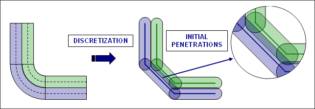
Fig. 5.13: Initial penetrations due to discretization
Option Inacti
Special treatment for initial penetrations can be accomplished through the use of the Inacti flag. It is possible to remove penetrated nodes from the interface or to remove the master segments relating to the penetrated nodes. Both treatments allow getting rid of initial penetrations very easily, but they may lead to poor results if the number of penetrated nodes is large.
By setting Inacti to 3, allows RADIOSS Starter to automatically modify the coordinates of penetrated nodes to avoid initial penetrations. Special care must be taken when doing so, since this operation can lead to initially constrained springs.
It is also possible to obtain a variable gap in time by setting Inacti to 5. The following illustration (Fig. 5.14) explains how the effective gap is updated taking into account the previous penetrations.
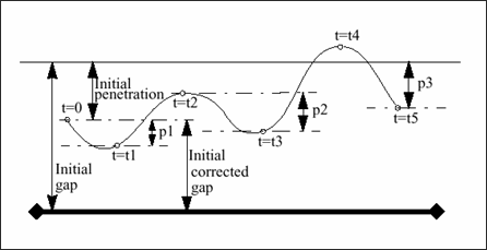
Fig. 5.14: Variable gap in time
At t=0, if a node is initially penetrated, its gap is automatically corrected. Then this “initial corrected gap” will be increased every time the node is moving away from the master segment. This option is mainly used for unfolding the airbag, it allows a decent time step at the beginning of the unfolding, whereas nodes are all highly penetrated.
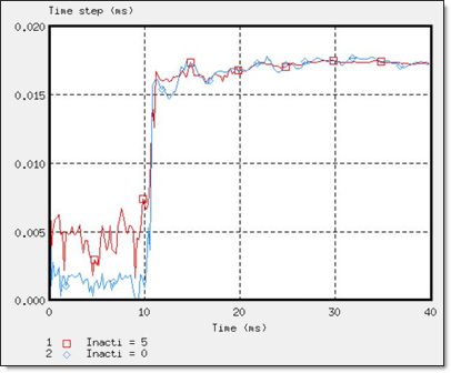
Fig. 5.15: Time step using Inacti=5
To avoid high frequency effects Inacti = 6 is recommended instead of Inacti =5.
Option Fpenmax
There is Fpenmax (Maximum fraction of initial penetration), which used to deal with big initial penetration. Node stiffness will be deactivated, if Pene > Fpenmax * Gap, whatever the value of Inacti.
Option Igap=3 + %mesh_size
With Igap= 3 and %mesh_size, the size of the mesh can be taken into account to avoid initial penetrations. In this case, the variable gap is computed as:
max {Gapmin, min[Fscalegap * (gs + gm), %mesh_size * (gs_l + gm_l), Gapmax]}
gm_l is the length of the smaller edge of element
gs_l is the length of the smaller edge of elements connected to the slave node
Option Irem_gap
The option Irem_gap is used to deactivate slave nodes which close (Curvilinear Distance < gap * ) to elements. This option is useful for self-impact contact when mesh size is very small.
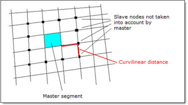
Fig. 5.15-1: Irem_gap definition
| Note: | When dealing with initial penetrations, it is strongly advised to remove initial penetrations during the creation of the FE model, using pre-processing tools like HyperMesh and HyperCrash depenetrators. |
|
Interface Stiffness
Like the other interface types, when using the penalty method, the interface has spring stiffness as a slave node penetrates the gap; however the reaction force is computed with much better approximation. The force variation versus penetration of a node is nonlinear, due to the increasing stiffness.
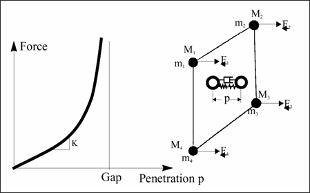
Fig. 5.16: Interface force variation in Interface type 7
The interface stiffness (K) is not constant, it increases with the penetration. Moreover, there is a viscous damping acting on the rate of penetration. The contact force is then computed as:
The instantaneous stiffness is then computed as:
Nodal time step can be seriously affected if penetration is large. The stiffness, used to compute the nodal time step takes into account the interface stiffness.
There are two ways to decrease the interface stiffness:
| • | increasing the initial stiffness (through the use of the flag Stfac) |
Both methods allow absorbing more energy by contact and smoothing the impact. Increasing the gap will allow nodes to slow down over a larger distance, therefore the penetration is reduced.
Comments
| 1. | Even if an elementary time step is chosen for the simulation, a nodal time step is automatically computed if there is an interface TYPE 7. The lowest time step is applied for the simulation. |
| 2. | Contrary to interface TYPE 5, a Stfac smaller than 1.0 produces a large penetration at the first touch and results in high interface stiffness and reaction force. To avoid high penetration, a Stfac greater than or equal to 1.0 is recommended. |
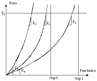
Fig. 5.17: Force vs. Penetration curves
Although, increasing the initial stiffness leads to a smaller time step at the beginning of the penetration, it will increase the time step if penetration is large.
Friction
Several friction formulations are available within RADIOSS. The simplest one, which is also the most used, is the Coulomb friction law. This formulation provides accurate results in crash analysis and requires just one parameter (Coulomb friction coefficient,  ).
).
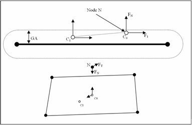
Fig. 5.18: Normal and tangential forces applied to a node
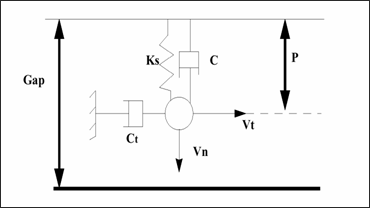
Fig. 5.19: Adhesion force computation
The default value for  is 0 (no friction between surfaces). To compute the friction force, the default friction penalty formulation is a viscous one, based on the tangential velocity. During sliding penetrate the node goes from position C0 (contact point at time t) to C1 (contact position at time
  ). As the contact is viscous, a viscous coefficient Ct is introduced to compute the adhesion force:

Where,  , K is the instantaneous interface stiffness. VISF is the critical damping coefficient on interface friction, and M is the master node mass.
Once the adhesion force (Fad) is computed, if it is lower than  , the friction force is unchanged equaling Fad and sticking will occur. If the adhesion force is greater than
  , then the friction force is reduced and equals
  .
.
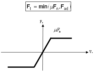
Fig. 5.20: Friction force computation
If sliding occurs at a very low speed (for example: quasi-static simulation), the viscous formulation will not work, as the friction force is computed upon the tangential speed. To overcome this limitation, a new friction penalty formulation is available based on tangential displacement (stiffness incremental formulation). This method introduces an artificial stiffness, K to calculate the variation of the friction force:

Where,  is the tangent displacement.
Therefore, contrary to the previous formulation, the stiffness formulation is able to compute the proper friction force even at a low speed. The following example illustrates this point. If an imposed displacement is applied to a part (a 3D cube) at a low speed ( 0.01 m/s), the viscous formulation will not work; whereas the stiffness formulation based on the tangential displacement will (Fig. 5.21).
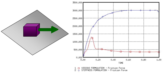
Fig. 5.21: Viscous formulation vs Stiffness formulation
Other friction formulations are available, their principle is similar to the Coulomb friction law. RADIOSS first computes an adhesion force, which is then compared to  . Their differences lie in the friction coefficient (
 ) which is not constant anymore, but function on the pressure of the normal force on the master segment and on the tangential velocity of the slave node. Depending on the flag Ifric, three new friction formulations are available:
Generalized Viscous Friction Law

Darmstad Friction Law
Renard Friction Law
| Note: | Friction filtering is available for all friction formulations and allows you to smooth the friction force (see the RADIOSS Starter Input Manual for more details). |
|
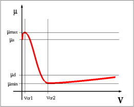
Fig. 5.22: Graphical representation of Renard friction model
Heat exchange
In interface type 7 there are three heat exchanges: heat transfer, radiation and heat friction are allowed by Ithe=1.
For heat transfer between slave and master with Iform_the, two different heat transfer can be defined. One is set constant temperature in interface where, heat exchange is only between this interface and shell slave side. The other is heat exchange between all pieces in contact.
If Frad ≠ 0, then radiation is computed inside of distance Drad (max. distance for radiation computation). It is recommended to not set too high of a value for Drad, otherwise RADIOSS Engine performance may be reduced.
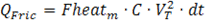
Using Fheats and Fheatm frictional sliding energy will be converted into heat. Since friction heat is divided between slave and master side, generally Fheats + Fheatm < 1.0. The frictional heat QFric is defined:
If Iform=2 (a stiffness formulation):
Slave side:
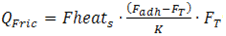
Master side:
 (Ithe_form=1)
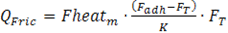
If Iform=1 (a penalty formulation):
Slave side:
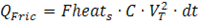
Master side
 (Ithe_form=1)
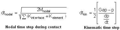
Interface Time Step Control
The previous section explains that the time step can be seriously reduced during contact since stiffness is added to all penetrated nodes. Moreover, to prevent any node from going through the master segment during one cycle, a kinematic time step is also computed. If the node impact velocity is high enough to pass through the segment on one cycle, RADIOSS reduces the time step in order to apply the penalty force when the node is in the gap distance. If p is the penetration distance, then dp/dt is the penetration speed and the kinematic time step is necessary time for the node to go over half of the distance between the node and the segment. The nodal time step is also computed to ensure the numerical stability. The smallest time step is then used for the simulation.
| Note: | Regarding the impact velocities in automobile crash simulations, kinematic time step cannot be activated. Its activation may be due to an incoherency in the model. |
|
If for some reason a node is highly penetrated, either the nodal time step or the kinematic time step may be very low. Then, it is possible to release this node from the interface using the option /DT/INTER/DEL in the engine file. All nodes reaching dtmin will be removed from the interface.
| Note: | This option may be useful in order to keep a decent time step during contact, but if the number of released nodes is too large, poor results can be expected. Take note of the following message displayed in the Engine output file: |
**WARNING MINIMUM TIME STEP XXX IN INTERFACE 1
REMOVE SLAVE NODE XXX FROM INTERFACE
|
|
Huge Increase in Mass
The use of mass scaling (/DT/NODA/CST) may lead to a mass instability. As a node penetrates, its global stiffness increases (the instantaneous interface stiffness, Kt is added); therefore, its nodal time step decreases. In order to match the minimum time step, RADIOSS adds the needed mass to the node. Unfortunately, this added mass increases the kinetic energy and the penetration gets bigger.
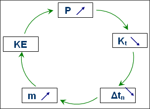
Fig. 5.23: Effect of mass scaling on interface type 7
Unless the interface is able to stop the penetration, the added mass (due to mass scaling) will keep on getting bigger and bigger. Therefore, the computation is likely to stop, since the mass variation may get huge very quickly (few cycles). If this is the case, the interface should be modified:
| • | initial stiffness can be increased |
| • | mesh should be modified to be refined and uniform in the contact zone |
Soft Part Against Hard Part
The default stiffness value computed by RADIOSS is often suitable to avoid very high penetration, leading to the time step dropping. When contact occurs between similar materials, there is no problem using the default stiffness; except when the materials are different. For instance, when mild steel impacts soft foam, the default stiffness may be too low to avoid a large penetration. When such contacts are willing to occur, it is advised to first compute the ratio of the slave material stiffness over the master material stiffness. If this ratio is greater than 100, a scale factor (flag Stfac) equal to this ratio should be used to increase the interface stiffness.
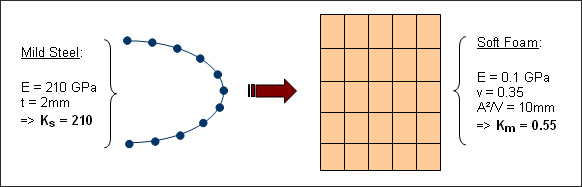
Fig. 5.24: Impact between steel and foam
Figure 5.24 shows contact between mild steel and soft foam. The ratio of stiffness is greater than 380, in such a case where the master side is the soft side, the flag Stfac may be set to 380 to avoid very high penetrations.
Locking Due to Edge to Edge Impact
Interface type 7 does not deal with edge to edge impact. The limitation of this interface during the edge to edge contact is illustrated in Fig. 5.25.
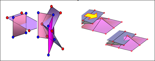
Fig. 5.25: Edge to edge contact
When the mesh is fine enough, edge to edge penetration is often followed by a node to shell contact. The main problem with edge to edge impact is the locking situations. If there is a change of load after edge penetration, locking is unavoidable since a node to surface contact is detected (Fig. 5.26). This usually leads to high penetration; therefore, the analysis comes to a standstill as time step is reduced. If locking occurs, the use of interface type 11 in this area is necessary to solve the problem.
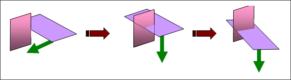
Fig. 5.26: Locking after edge penetration
Generation of Tangential Force
A tangential force can be generated when a penetrated node is sliding without friction. This behavior is due to the gaps overlapping around the edges. Figure 5.27 illustrates that by the cylindrical gap around the edges, the force is no longer normal to the shell mid-surface.
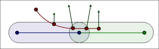
Fig. 5.27: Generation of tangential force
| Note: | No problems were observed in crash simulations, but in metal forming where friction is very important this can seriously decrease the accuracy. |
|
Comments
| 1. | It is always advised to post-process the contact forces. If they are too large, taking into account the physical understanding, the model must be checked. |
| 2. | To post-process the forces for symmetric contact, the interface can be split into four interfaces. For example, for two parts A and B, you can create: |
| • | Interface 1 with A Slave and B Master |
| • | +Interface 2 with A Master and B Slave |
| • | +Interface 3 with A Master and Slave |
| • | +Interface 4 with B Master and Slave |
Gap Warning When Modeling Auto-Contact
This warning should only be taken into account of a self-impacting interface. When simulating auto-contact, it is strongly advised to use a minimum gap of at least one half of the smallest segment edge. The message means that at least one element on the master side has a side length less than twice the GAP, and there is an over-stiffening risk.
WARNING ID: 94
** WARNING IN INTERFACE GAP
INPUT GAP 1.7
HOWEVER GAP IS RECOMMENDED TO BE LESS THAN 1
|
Below (Fig. 5.28) illustrates a self-impacting interface for which the GAP equals half the side length of an element. If this element is compressed more than 50%, the red node enters into the gap of the neighboring element; a self-contact is then detected which should not be the case. This leads to over-stiffening of the structure.
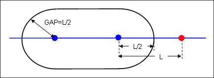
Fig. 5.28: Recommended gap when modeling auto-contact
If the side length, L of an element is lower than the GAP, a self-contact will even be computed from the beginning of the computation.
Such a situation can be accepted if it is an exception, but not for frequent cases over the self-impacting interface. It is possible to localize the source of this message by using a pre-processor and selecting the elements through size criteria.
Rupture
When rupture is modeled and elements are expected to fail, it is important to deal with failed elements defined either as a master segment, or as slave nodes. When an element is deleted, its corresponding segment is still taken into account and its nodes are still considered for contact. This behavior can lead to a huge error, as deleted elements have no stiffness; therefore, it is recommended to set the flag Idel to 2 when failure is expected. This flag will remove any failed element from the master surface and corresponding nodes will be removed from the slave nodes list.
Comment
| 1. | The Idel flag exists as of RADIOSS V51. For older versions, refer to /DELINT/ON. |


