|
»Click here to display Table of Contents«
|

/INTER/LAGDT/TYPE7 |

|

|

|

|
|
/INTER/LAGDT/TYPE7 |
|
|

|

|
|
»Click here to display Table of Contents«
|
/INTER/LAGDT/TYPE7 |
|
|
|
|
|
/INTER/LAGDT/TYPE7 |
|
|
|
|
Block Format Keyword
/INTER/LAGDT/TYPE7 - Interface Type 7 with Constant Minimum Time Step
Description
Describes the interface TYPE7 with constant minimum time step. Which means same behavior as interface TYPE7 with possible switch to Lagrange multiplier formulation, if minimum time step defined with /DT/INTER/CST is reached. The main limitations are:
| • | Same limitation as interface TYPE7 with Lagrange multiplier formulation. |
| • | Friction is not working after switching into Lagrange multiplier formulation. |
| • | Not yet compatible with SPMD. |
Format
(1) |
(2) |
(3) |
(4) |
(5) |
(6) |
(7) |
(8) |
(9) |
(10) |
/INTER/LAGDT/TYPE7/inter_ID/unit_ID |
|||||||||
inter_title |
|||||||||
grnd_IDs |
surf_IDm |
Istf |
|
Igap |
|
Ibag |
Idel |
|
|
Fscalegap |
Gapmax |
|
|
|
|
|
|
||
Stmin |
Stmax |
|
|
|
|
|
|
||
Stfac |
Fric |
Gapmin |
Tstart |
Tstop |
|||||
IBC |
|
|
Inacti |
VISS |
VISF |
Bumult |
|||
Ifric |
Ifiltr |
Xfreq |
Iform |
|
|
|
|
|
|
Read this input only if Ifric > 0 (Optional)
(1) |
(2) |
(3) |
(4) |
(5) |
(6) |
(7) |
(8) |
(9) |
(10) |
C1 |
C2 |
C3 |
C4 |
C5 |
|||||
Read this input only if Ifric > 1 (Optional)
(1) |
(2) |
(3) |
(4) |
(5) |
(6) |
(7) |
(8) |
(9) |
(10) |
C6 |
|
|
|
|
|
|
|
|
|
|
|
The values given in Line 4 are ignored if Igap ≠ 2.
Where,
Istf = 2, Istf = 3, Istf = 4, Istf = 5,
When master segment lies on a shell or is shared by shell and solid
When master segment lies on a solid:
Where, S is the segment area, V is the volume of the solid, B is the Bulk Modulus
When node is connected to a shell element:
When node is connected to a solid element:
There is no limitation to the value of stiffness factor (but a value larger than 1.0 can reduce the initial time step).
While,
Where,
with t: thickness of the master element for shell elements gm = 0 for brick elements
gs = 0 if the slave node is not connected to any element or is only connected to brick or spring elements.
with t: largest thickness of the shell elements connected to the slave node.
If the slave node is connected to multiple shells and/or beams or trusses, the largest computed slave gap is used. The variable gap is always at least equal to Gapmin.
Inacti = 5 is recommended for airbag simulation deployment Inacti = 6 is recommended instead of Inacti =5, in order to avoid high frequency effects into the interface.
Where, p is the pressure of the normal force on the master segment, V is the tangential velocity of the slave node.
The following formulations are available:
Where,
If Ifiltr ≠ 0 , the tangential forces are smoothed using a filter:
Where
The filtering coefficient Xfreq should have a value between 0 and 1.
While an adhesion force is computed as follows:
While an adhesion force is computed as follows:
Where, Vt is contact tangential velocity |

 ,
,  ,
,  for truss and beam elements, with
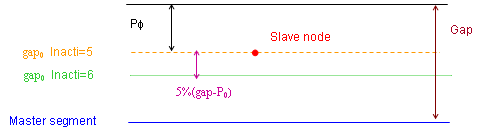
 if
if  if
if  if
if 
 and
and