|
»Click here to display Table of Contents«
|

Linear Buckling Analysis |

|

|

|

|
|
Linear Buckling Analysis |
|
|
|

|
|
»Click here to display Table of Contents«
|
Linear Buckling Analysis |
|
|
|
|
|
Linear Buckling Analysis |
|
|
|
|
The problem of linear buckling in finite element analysis is solved by first applying a reference level of loading, PRef , to the structure. A standard linear static analysis is then carried out to obtain stresses which are needed to form the geometric stiffness matrix KG. The buckling loads are then calculated by solving an eigenvalue problem:
![]()
Where, K is the stiffness matrix of the structure and ![]() is the multiplier to the reference load. The solution of the eigenvalue problem generally yields n eigenvalues
is the multiplier to the reference load. The solution of the eigenvalue problem generally yields n eigenvalues ![]() , where n is the number of degrees-of-freedom (in practice, only a subset of eigenvalues is usually calculated). The vector x is the eigenvector corresponding to the eigenvalue.
, where n is the number of degrees-of-freedom (in practice, only a subset of eigenvalues is usually calculated). The vector x is the eigenvector corresponding to the eigenvalue.
The eigenvalue problem is solved using a matrix method called the Lanczos method. Not all eigenvalues are required. Only a small number of the lowest eigenvalues are normally calculated for buckling analysis.
The lowest eigenvalue ![]() is associated with buckling. The critical or buckling load is:
is associated with buckling. The critical or buckling load is:
![]()
In order to run a linear buckling analysis, an EIGRL bulk data entry needs to be given because it defines the number of modes to be extracted. The EIGRL card needs to be referenced by a METHOD statement in a SUBCASE in the subcase information section. In addition, it is necessary to use a STATSUB card to reference the appropriate referential static loading, fre SUBCASE. STATSUB cannot refer to a subcase that uses inertia relief.
The buckling analysis will ignore zero-dimensional elements, MPC, RBE3, and CBUSH elements. These elements can be used in buckling analysis, but they do not contribute to the geometric stiffness matrix, KG. By default, the contribution from the rigid elements to the geometric stiffness matrix is not included. You have to add PARAM,KGRGD,YES to the bulk data section to include the contribution of rigid elements to the geometric stiffness matrix.
In addition, through the EXCLUDE subcase information entry, you may decide to omit the contribution of other elements to the geometric stiffness matrix, effectively allowing you to control which parts of the structure are analyzed for buckling. The excluded properties are only removed from the geometric stiffness matrix, resulting in a buckling analysis with elastic boundary conditions. This means that the excluded properties may still be showing movement in the buckling mode.
Buckling analysis cannot be performed if the referential static loading subcase uses inertia relief. In such cases, the stiffness matrix is positive semi-definite and the buckling eigenvalue solution ends in singularity.
Some one-dimensional and shell elements can use offset to “shift” the element stiffness relative to the location determined by element’s nodes. For example, shell elements can be offset from the plane defined by element nodes by means of ZOFFS. In this case all other information, such as material matrices or fiber locations for the calculation of stresses, are given relative to the offset reference plane. Similarly, shell results, such as shell element forces, are output on the offset reference plane.
Offset is applied to all element matrices (stiffness, mass, and geometric stiffness), and to respective element loads (such as gravity). Hence, in principle offset can be used in all types of analysis and optimization, including linear buckling. However, caution is advised when interpreting the results. Without offset, a typical simple structure will bifurcate and loose stability “instantly” at the critical load. With offset, though, the loss of stability is gradual and asymptotically reaches a limit load, as shown below in figure (b):
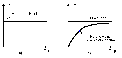
In practice then, the structure with offset can reach excessive deformation before the limit load is reached. (Note that more complex structures, such as frames or structures experiencing bending moments, buckle via limit load, even in absence of ZOFFS on the element card). Furthermore, in a fully nonlinear approach, additional instability points may be present on the limit load path.