This example involves a rectangular, thin-walled container used for storing fluid. The objective is to minimize the outward bulging of the sides of the container caused by the pressure of its contents. Additionally, the maximum outward displacement of the side panels must be below a given value.
The model is constrained for displacement in all directions at the four lower corners, but is free to rotate about those constraints. The loading is a distributed pressure through the area shown in green. The pressure is higher at the bottom of the vessel.
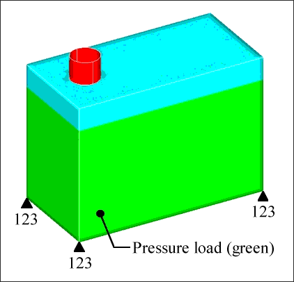
Loads and constraints on rectangular pressure vessel.
The design domain includes the entire box with the exception of the filling hole on the top (shown in red). All of the elements in the design domain are placed in the same component and reference the same material property. The normal vectors for all of the elements in the design domain are pointing outward. The topology variables are set up with the following DTPG card:
(1)
|
(2)
|
(3)
|
(4)
|
(5)
|
(6)
|
(7)
|
(8)
|
(9)
|
(10)
|
DTPG
|
1
|
PSHELL
|
1
|
|
|
|
|
|
|
+
|
15.0
|
60.0
|
NO
|
4.5
|
NORM
|
|
|
NONE
|
|
|
PATRN
|
10
|
7229
|
|
|
7209
|
|
|
|
The minimum bead width is set at 15.0mm, which is roughly the size of three elements. The draw angle is set at 60 degrees, and the draw depth is set at 7.5mm. The shape variable draw vectors are determined according to the element’s normal direction. No buffer zone has been selected between the filling cap and the rest of the model. No grids are to be skipped. Therefore, the nodes (where the constraints are applied) are associated with shape variables and are free to move.
The third line of the DTPG card defines the pattern grouping option, in this case it is a plane of symmetry. For this model, symmetry was enforced by dividing the box in half lengthwise. The vector that defines the plane of symmetry was created pointing away from the side with the non-design filler cap to prevent the absence of design variables from being reflected to the design side.
Optimization objective function and constraints are set up as follows.
In the header, the following cards are added inside the subcase definition:
In the bulk data the following cards are added:
DRESP1
|
1
|
obj
|
COMP
|
|
|
|
|
|
DRESP1
|
2
|
swall1
|
DISP
|
|
|
7
|
|
7332
|
DRESP1
|
3
|
swall2
|
DISP
|
|
|
7
|
|
9783
|
DRESP1
|
4
|
fwall
|
DISP
|
|
|
7
|
|
9162
|
DRESP1
|
5
|
bwall
|
DISP
|
|
|
7
|
|
8813
|
DRESP1
|
6
|
bottom
|
DISP
|
|
|
7
|
|
11028
|
DCONSTR
|
101
|
2
|
|
10.0
|
|
|
|
|
DCONSTR
|
101
|
3
|
|
10.0
|
|
|
|
|
DCONSTR
|
101
|
4
|
|
1.0
|
|
|
|
|
DCONSTR
|
101
|
5
|
|
1.0
|
|
|
|
|
DCONSTR
|
101
|
6
|
|
5.0
|
|
|
|
|
The objective is to minimize compliance for the pressure load case, which is the same as minimizing the strain energy of the entire model. The displacement of the center point of each of the five loaded surfaces was constrained to be less than a given value.
OptiStruct generated the following solution for the problem:
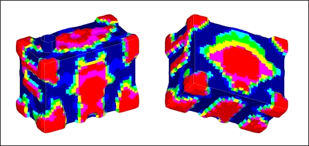
OptiStruct topography solution for pressure vessel, front and rear views.
All of the optimization constraints are met for the model. The red areas represent the bead reinforcements that OptiStruct created to increase the stiffness of the model. Circular or oval reinforcement beads are generated for the large side panels and the bottom panel of the box.
Circular and oval beads are very effective in stiffening the panels against a distributed or central load. This is due to the fact that bending in the central areas of the panels is occurring in two directions, both vertically and horizontally. Straight beads provide stiffness for bending in one direction, but would be vulnerable to kinking in the other. Round beads provide stiffness without kinking. Bulbous beads are created at the eight corners of the model, anchoring the sides of the box together and allowing each side of the box to gain support from the adjacent sides.
By changing the draw height on the DTPG card from 4.5 to –4.5, the direction of the beads can be changed from outward to inward.
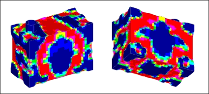
OptiStruct topography solution for pressure vessel, reversed bead directions.
The bead pattern for the inward bead model is almost a complete reflection of the one that OptiStruct created for the outward bead model. The areas that are not pushed out in the outward bead model are pushed in for the inward bead model, generating the same basic structure.
For the input file sample, see <install_directory>/demos/hwsolvers/optistruct/pressurebox.fem.
See Also:
Example Problems for Topography Optimization


