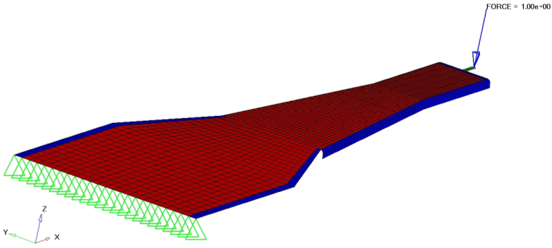
This tutorial performs a combined topology and topography optimization on a slider suspension using OptiStruct. The objective is to increase the stiffness of the slider suspension and make it lighter at the same time. This requires the use of both topology and topography optimization.
The finite element model of the slider suspension contains force and boundary conditions. The structure is made of quad elements and has both linear statics and normal modes subcases (loadsteps). Steps are described to define topology and topography design space, responses, constraints, and objective function. The optimized structure will be stiffer for both linear statics and normal modes subcases and will have beads and less material.

Disk drive slider
Problem Statement
Perform combined topology and topography optimization on a disk drive slider suspension to maximize the stiffness and weighted mode. The lower bound constraint on the seventh mode is 12 cycles/ms.
Objective function:
|
Minimize the combined weighted compliance and the weighted modes.
|
Constraints:
|
7th Mode > 12 cycles/ms.
|
Design variables:
|
Element densities and nodes topography.
|
In this tutorial, you will learn to:
| • | Set up a combined optimization using HyperMesh |
| • | Post-process optimization results in HyperView |
Exercise
Step 1: Set the User Profile and Import a Finite Element Model
| 2. | Select OptiStruct in the User Profiles dialog and click OK. This loads the user profile. It includes the appropriate template, macro menu, and import reader, paring down the functionality of HyperMesh to what is relevant for generating models for OptiStruct. |
| 3. | From the File menu on the toolbar, select Import > Solver Deck. An Import tab is added to your tab menu. |
| 4. | Choose the proper File type: OptiStruct. |
| 5. | Click the Select Files icon  and open the combined.fem file you saved to your working directory from the optistruct.zip file. Refer to Accessing the Model Files. and open the combined.fem file you saved to your working directory from the optistruct.zip file. Refer to Accessing the Model Files. |
| 8. | Click Close to close the Import tab menu. |
Step 2: Set up the Topology Design Space
| 1. | From the Analysis page, select the optimization panel. |
| 3. | Verify that you are in the create subpanel. |
| 4. | Click props, select 1pin, and click select. |
| 5. | For desvar =, enter the name pin. |
| 6. | Change type: to PSHELL. |
| 7. | Verify base thickness is 0.0. |
| 9. | Click props, check only 3bend and click select. |
| 10. | For desvar =, enter the name bend. |
| 11. | Verify base thickness is 0.0. |
Step 3: Set up the Topography Design Space
| 2. | Verify that you are in the create subpanel. |
| 3. | Click props, check 1pin and 3bend, and click select. |
| 4. | For desvar=, enter the name tpg. |
| 6. | Select the bead params subpanel. |
| 7. | For minimum width=, enter a value of 0.4; for draw angle=, 60; and for draw height=, 0.15. |
| 8. | Toggle draw direction: to normal to elements. |
| 9. | Toggle boundary skip: to load & spc. |
Use 1-plane symmetric beads, as it is the simplest and can be symmetric at the same time.
| 12. | Go to the pattern grouping subpanel and set pattern type: to 1-plane sym. |
| 13. | Click anchor node, enter 41, and press ENTER. |
| 14. | Click first node, enter 53, and press ENTER. |
| 16. | Select the bounds subpanel. |
| 17. | Verify the bounds are as follows: |
upper bound = 1.0, lower bound = 0.0.
Step 4: Create Responses for Optimization
Since this problem is a combined linear static and normal mode analysis, you are trying to minimize compliance and increase frequency for the two load cases, while constraining the seventh frequency. Therefore, two responses are defined: comb and freq.
| 1. | Select the responses panel. |
| 2. | For response =, enter the name freq. |
| 3. | Change the response type to frequency. |
| 4. | For Mode Number, enter a value of 7. |
| 6. | For response =, enter the name comb. |
| 7. | Change the response type to compliance index. |
| 8. | Click loadsteps and activate force. |
| 9. | Make sure that the option to define normalizing factor is toggled to autonorm. |
| 10. | Enter the mode numbers and their corresponding weights using the following chart. |
Mode
|
Weight
|
1
|
1.0
|
2
|
2.0
|
3
|
1.0
|
4
|
1.0
|
5
|
1.0
|
6
|
1.0
|
Step 5: Define Constraints
| 2. | For constraint =, enter the name frequency. |
| 3. | Check lowerbound and enter a value of 12. |
| 4. | Click response= and select freq. |
| 5. | Click loadsteps and click the frequency checkbox, then click select. |
Step 6: Define the Objective Function
| 2. | Verify that objective is set to min. |
| 3. | Click response = and select comb. |
Step 7: Define the Optimization Control Cards
| 2. | Click the checkbox for MINDIM to activate it and enter a value of 0.25. |
Minimum member size is generally recommended to avoid checkerboarding. It also ensures that the structure has the minimum dimension specified in this card.
| 3. | Click the checkbox for MATINIT to activate it and enter a value of 1.0. |
MATINIT declares the initial material fraction in a topology optimization. MATINIT has several defaults based upon the following conditions: If mass is the objective function, the MATINIT default is 0.9. With constrained mass, the default is reset to the constraint value. If mass is not the objective function and is not constrained, the default is 0.6.
| 4. | Click return twice to exit the panel. |
Step 8: Set Up Mode Tracking
During optimization, the frequencies and their mode shape may change order due to the change in element densities and other design changes. To overcome this, define a parameter to track the frequencies so that only the intended frequencies are tracked during optimization runs.
| 1. | Click control cards and click next twice. |
| 3. | In the panel, check MODETRAK. |
| 4. | In the card panel, set MODET_V1 to Yes. |
Note that the PARAM button is now green, indicating that it is active.
| 6. | Click return to go back to the Analysis page. |
Step 9: Submit the OptiStruct Job
| 1. | From the Analysis page, click OptiStruct. |
| 2. | For export options: toggle to all. |
| 3. | For run options: toggle to optimization. |
| 4. | For memory options: toggle to memory default. |
| 5. | Click save as following the input file: field. |
| 6. | Select the directory where you would like to write the OptiStruct model file and enter the name for the model, comb_complete.fem, in the File name: field. For OptiStruct input decks .fem is the suggested extension. |
The name and location of the file displays in the input file: field.
| 8. | Click OptiStruct. This launches an OptiStruct run in a seperate shell (DOE or UNIX) which appears. |
If the optimization was successful, no error messages are reported to the shell. The optimization is complete when the message Processing complete appears in the shell.
Post-process Optimization Results in HyperView
Step 10: Post-process the Shape Change Result (Topography)
| 1. | When the message Job Complete is received in the HyperWorks Solver View window, close the command window to return to HyperMesh. |
| 2. | In HyperMesh, click HyperView (from the OptiStruct panel) to launch HyperView. The HyperView GUI window opens and the results get loaded automatically in HyperView. |
| 3. | Click the Deformed toolbar icon  . . |
| 4. | By clicking on the drop-down menus next to each option, for Result type, select Shape Change(v); for Scale, select Scale factor; and for Type, select Uniform. |
| 6. | Below the Undeformed shape: section, click the drop-down menu next to Show and select None. |
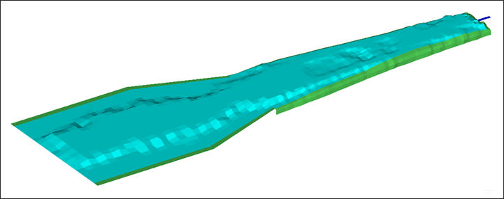
| 7. | Click Apply to display the shape change because of topography optimization. |
| 8. | In the Result browser, open the Load Case and Simulation Selection drop-down menu and select the 25th iteration. |

Topography result applied on slider suspension.
Step 11: Contour of the Optimum Material Distribution (Topologic)
| 1. | Click the Contour toolbar icon  . . |
| 2. | Select the first drop-down list below Result Type and select Element Thicknesses(s). |
| 3. | Select the second drop-down list below Result Type and select Thickness. |
| 4. | Select Simple in the field below Averaging method. |
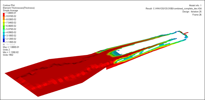
| 5. | Click Apply to display the density contour. |
Step 12: Add Iso-surface of the Optimum Material Distribution (Topologic)
| 1. | Click the Iso Value toolbar icon  . . |
| 2. | For the first drop-down list below Result Type, select Element Densities (s) and Density in the second list. |
| 3. | Make sure that Above is selected in the field next to Show values. |
| 4. | Click Apply to display the density iso-surface plot. |
| 5. | Enter 0.3 in the field next to Current value and press ENTER. |
An iso-surface plot is displayed in the graphics window. Those parts of the model with a density greater than the value of 0.3 are shown in with density contour, the rest are removed from the display.

See Also:
OptiStruct Tutorials


