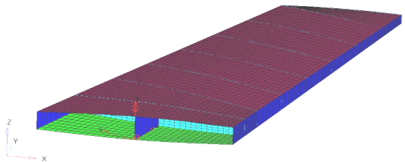
Composite wing model.
One of the advantages with composite materials is that the structural performance can be controlled precisely by choosing the appropriate ply thickness, ply orientation, stacking sequence, ply materials, and so on. The ability to vary many different parameters provides greater flexibility, but at the same time it is tougher to optimize the part as the number of design variables increases many fold. OptiStruct has the ability to directly or indirectly optimize the ply thickness, ply orientation and stacking sequence for composite structures.
Free-size optimization handles the thickness of each ply in each element as a design variable and optimizes the structure by determining the optimal thickness distribution for each ply in the laminate. Refer to the Free-Size Optimization and Composite Topology and Free-size Optimization pages of the OptiStruct User's Guide help for more details.
For several reasons, every composite manufacturer has their own manufacturability standards for the laminated composites. These additional manufacturing constraints are to be included with free-size optimization to achieve an acceptable manufacturing solution. OptiStruct supports different manufacturability constraints that can be defined with free-size optimization. This tutorial helps explain the procedure used to define the manufacturing constraints in the free-size optimization of composite structures.
The optimization problem for this tutorial is stated as:
Objective:
|
Minimize the Mass.
|
Constraints:
|
Displacement of selected 6 nodes < 3 mm.
|
Design variables:
|
Thickness of each ply of each element in the design space.
|
In this tutorial, a free-size optimization with the following manufacturing constraints will be set up:
| • | Minimum laminate thickness of 0.2 |
| • | Ply thickness should be at least 10% and at most 60% of total laminate thickness, defined for all the plies in the design space |
| • | The thickness of ply with a ply angle of 45 degrees to be same as the thickness of ply with a ply angle of -45 degrees |
In this tutorial, you will learn to:
| • | Set up a free-size optimization with manufacturing constraints |
| • | Post-process the free-size optimization results |
Exercise
Step 1: Launch HyperMesh Desktop, Load the User Profile and Retrieve the File
| 1. | Launch HyperMesh Desktop. |
| 2. | Choose OptiStruct in the User Profiles dialog and click OK. This loads the user profile. It includes the appropriate template, macro menu, and import reader, paring down the functionality of HyperMesh to what is relevant for generating models for OptiStruct. |
User Profiles GUI can also be accessed from the Preferences menu on the toolbar.
| 3. | From the File menu on the toolbar, select Open. |
| 4. | Select the Composite_Wing.hm file you saved to your working directory from the optistruct.zip file. Refer to Accessing the Model Files. |
| 5. | Click Open to load the model into the HyperMesh session. |
Step 2: Review the Model Setup
The model is already set up for analysis. The model properties, loads, boundary conditions, and loadsteps are already defined. The model has 15 components out of which the TopSkin and BottomSkin components are defined with the composite property PCOMP. The rest of the components are defined with PSHELL property which references the material property, Aluminum. In the following section, you will review the layup information for the TopSkin and BottomSkin components using the HyperLaminate panel.
Wing geometry
| 1. | From the 2D page, select the HyperLaminate panel. This opens the HyperLaminate GUI in which the ply lay-up information can be defined, reviewed and edited. Size design variables can also be set up in this panel for performing size optimization. |
| 2. | Expand the Laminates portion of the tree structure on the left-hand side of the screen. |
| 3. | Select the TopSkin component for review by clicking on the component name. This loads the TopSkin component properties in the Laminate definition section and Review section. The Laminate definition section shows the ply material, ply thickness, ply orientation, etc. which is shown graphically under the Review section. |
The same layup information is also defined for the BottomSkin component. In this tutorial, you will define free-size optimization on the TopSkin and BottomSkin components.
| 4. | From the File menu, select Exit. |
Exiting the HyperLaminate GUI and returning to HyperMesh.
Setting Up a Free-size Optimization with Manufacturing Constraints
Step 3: Create a Design Variable for Free-sizing Optimization
| 1. | From the Analysis page, select optimization to enter the panel. |
| 2. | Select free size to enter this panel. |
| 3. | Select the create subpanel using the radio button on the left. |
| 4. | Click desvar= and enter Skins. |
| 5. | Click the selection switch below type: and select PCOMP(G). |
| 6. | Click props, choose the TopSkin and BottomSkin properties, and click select. |
| 7. | Clicks create. This creates the design variable for free-sizing optimization. |
Step 4: Add a Minimum Dimension (mindim) Manufacturing Constraints for Free-size Optimization
| 1. | While still in the free size optimization panel, select the parameters subpanel. |
| 2. | Click desvars and select the Skins design variable created previously. |
| 3. | Toggle minmemboff for mindim =, and enter 5.0. |
This step defines the minimum member size control to be 5.0. Member size control gives you some control over the member size in the final free-size design and the resulting structure will have discrete members that are easy to interpret during post-processing.
Step 5: Add Minimum Thickness Manufacturing Constraints for Free-sizing Optimization
In this section, the percentage following manufacturing constraints needs to be defined.
| • | Minimum laminate thickness of 0.2. |
| • | A Minimum of 10% and a maximum of 60% thickness (of total laminate thickness) constraints defined for all the plies. This means that for each element, none of the plies will have thickness less than 10% or greater than 60% of the totals laminate thickness. |
| • | The thickness of ply with ply angle of 45 degree to be same as the thickness of ply with ply angle of -45 degree. |
| 1. | While still in the free size optimization panel, select the composites subpanel. |
| 2. | Click desvar= and select the Skins design variable created previously. |
| 3. | Under the laminate thickness: section, toggle minimum thickness off to minimum thickness =. |
| 4. | Enter 0.2 in the field that appears next to minimum thickness =. |
| 5. | Click update to update the above defined minimum laminate thickness constraint to the free-size design variable. |
| 6. | Click edit to open the panel. |
| 7. | Select PLYPCT by clicking in the box. |
| 8. | Click the switch below PLYPCT and select Specify Number. |
| 9. | Enter 4 in the field next to DSIZE_NUMBER_OF_PLYPCT=, to specify that ply percentage constraints will be defined on 4 plies. |
This opens 4 additional lines, as shown in the image below, in which you can enter the ply percentage constraints. The table below explains the 4 different fields in which ply percentage constraint is defined.
PANGLE
|
Ply orientation to which the PLYPCT constraints are applied.
|
PPMIN
|
Minimum ply percentage thickness for the PLYPCT constraint.
|
PPMAX
|
Maximum ply percentage thickness for the PLYPCT constraint.
|
PTMAN
|
Manufacturable ply thickness.
|
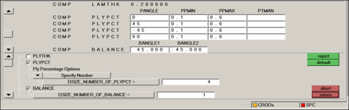
| 10. | In the first field next to COMP PLYPCT and below PANGLE, enter 0 to define that ply percentage constraints are defined for the ply with ply angle of 0 degree. Enter 0.1 for PPMIN and 0.6 for PPMAX. The PTMAN field can be left blank. |
The above step defines that for each element, the thickness of the ply with ply angle 0, should be no less than 10% or more than 60% of the total thickness.
| 11. | Similarly define the same constraints of 0.1 for PPMIN and 0.6 for PPMAX for the plies with ply angle 45, -45 and 90 as shown in the image above. |
| 12. | Similarly, activate BALANCE by clicking on the box, and define 1 in the field for DSIZE_NUMBER_OF_BALANCE=. |
The BALANCE constraint ensures that two plies will always be of equal thickness.
BALANCE
|
BALANCE flag indicating that a balancing constraint is applied.
|
BANGLE1
|
First ply orientation to which the BALANCE constraint is applied.
|
BANGLE2
|
Second ply orientation to which the BALANCE constraint is applied.
|
| 13. | In the field below BANGLE1, enter 45 and in the field below BANGLE2 enter -45. |
The above step defines that the plies with ply angle of 45 and -45 will always have the same thickness.
| 14. | Click return to return from the panel. |
| 15. | Click update to update the above defined manufacturing constraints to the free-size design variable. |
| 16. | Click return to return from the free size panel. |
Step 6: Create Displacements and Mass Responses
To create a displacement as a response, you will need to supply a meaningful name for the response, set the response type to displacement, select the nodes for which the response is defined, and select the type of displacement (dof).
| 2. | Click response= and enter disp. |
| 3. | Change the response type: to static displacement. |
| 4. | Click nodes to open the extended entity selection window and select by sets. |
| 5. | Click the box next to Nodes to select the set and click select. |
Notice that 6 nodes at the end side of the wing are selected.
| 7. | Click create to create the displacement response for the selected nodes. |
| 8. | Similarly, create another response with the name mass and a response type: of mass, with total for the option. |
| 9. | Click create to create the mass response. |
Step 7: Create Constraints on Displacement Responses
In this step, the upper and lower bound constraint criteria for the analysis are set.
| 1. | Select the dconstraints panel. |
| 2. | Click constraint= and enter disp_constr. |
| 3. | Check the box for upper bound only. |
| 4. | Click upper bound= and enter 2.0. |
| 5. | Select response= and set it to disp. |
| 7. | Check the boxes next to SubCase1 and SubCase2. |
| 10. | Click return to go back to the optimization panel. |
Step 8: Define the Objective Function
| 2. | The switch on the left should be set to min. |
| 3. | Click response= and select mass. |
| 5. | Click return twice to exit the optimization panel. |
Step 9: Run the Optimization Problem
| 1. | From the Analysis page, select OptiStruct. |
| 2. | Click save as, enter Wing_FreeSize_with_PLYPCT.fem as the file name, and click Save. |
| 3. | Click the run options: switch and select optimization. |
| 4. | Click OptiStruct to run the optimization. |
The message Processing complete appears in the window at the completion of the job. OptiStruct also reports error messages if any exist. The file Wing_FreeSize_with_PLYPCT.out can be opened in a text editor to find details regarding any errors. This file is written to the same directory as the .fem file.
| 5. | Close the Solver View window. |
Post-processing the Free-size Optimization Results
OptiStruct provides element thickness, ply thickness information for all iterations, and also writes out displacement and von Mises stress results for the linear static analysis. This section describes how to view the results in HyperView.
Step 10: View a Contour Plot of Element and Ply Thicknesses
| 1. | From the OptiStruct panel, click HyperView. |
This starts a new HyperView session. All of the result files in .h3d format are automatically loaded into HyperView. A message window appears with information about the model and result files loaded into HyperView.
| 2. | From the Results menu, activate the menu over Plot and click Contour. Choose Element thicknesses as the Result type; then choose the drop-down menu below and select Thickness. |
| 3. | Click Apply. This shows the contour of total laminate thickness for the selected iteration. |
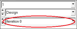
| 4. | In the left top portion of the GUI, click in the area circled below to open the Iteration selection pull-down and select the last design iteration result. The contoured thickness is the optimal laminate thickness distribution for the current design. |
Step 11: View Contour Plot Ply Thicknesses
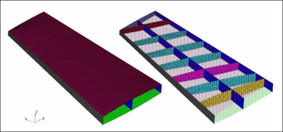
Since only the TopSkin and BottomSkin components are in the free-size design space and the thickness of only these two components are changing, it is convenient to view only these two components. Also, for easy visualization purposes, it is convenient to move the two surfaces apart as they are very close to each other.
| 1. | Click Iso  and click Apply to display the isometric view of the model. and click Apply to display the isometric view of the model. |
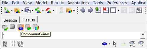
| 2. | In the Model browser, click the Component view icon  . . |
| 3. | Click the Isolate Shown icon  and then click BottomSkin and TopSkin in the component tree. and then click BottomSkin and TopSkin in the component tree. |
This leaves only these two components displayed.
| 4. | Click the Exploded View icon,  . . |
| 5. | Click Add to add a new explosion view. |
| 6. | Click one of the components in the graphics area to select it for translating. |
| 7. | Select X Axis for the Direction option under Translate:. Leave the default value of 5 in the Distance field. |
| 8. | Click the plus icon to move the selected component in the positive X direction and repeat until the component is moved enough to view both the components. |
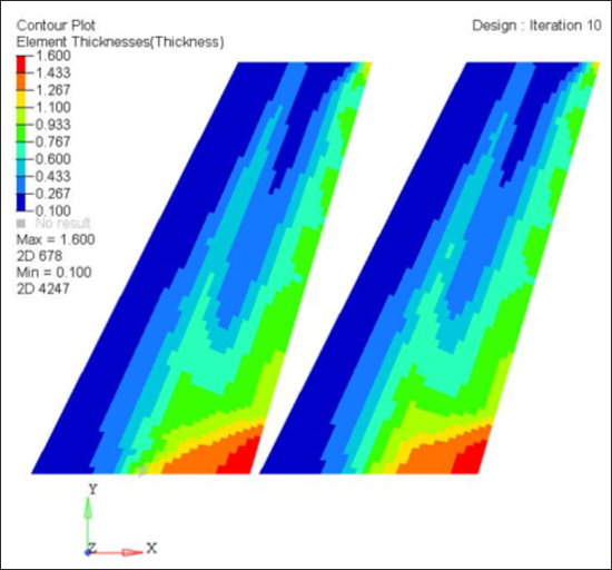
Laminate optimized thickness contour
| 9. | From the Results menu, activate the menu over Plot and click Contour. Choose Ply Thickness as the Result type and leave Thickness selected. |
| 10. | For Entity with Layer:, select 1, and click Apply. |
This shows the first ply thickness contour. You can repeat these steps to plot the thickness for Ply 2, Ply 3, and Ply 4 or Max, etc.
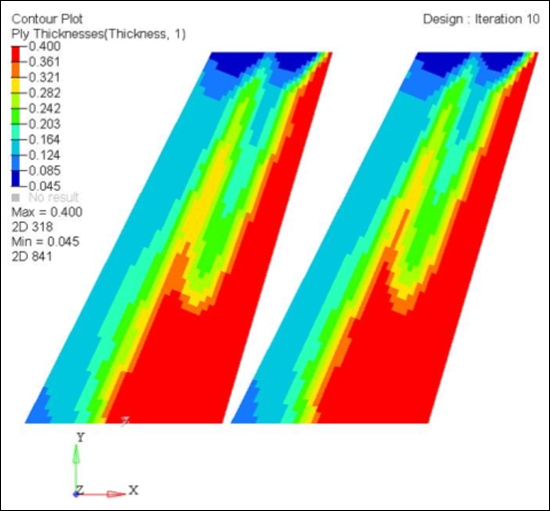
First ply optimized thickness contour
| 11. | Verify if all the manufacturing constraints (ply percentage, balance and minimum laminate thickness) are satisfied. Additionally, open the Wing_FreeSize_with_PLYPCT.out file in a text editor and verify that the displacement constraints are satisfied in the last iteration. |
See Also:
OptiStruct Tutorials


