This tutorial demonstrates how to set up the multi-body dynamics (MBD) size optimization of a rotating bar in HyperMesh and how to run the optimization job in OptiStruct. The structural model is shown in the figure below. Angular velocity at the revolute joint defined left end of the bar is 10*SIN(2*TIME) rad/sec. The objective is to minimize the maximum stress of the structure subject to certain mass specifications. The bar consists of five bar elements with a solid circle cross section (each element has its own PBARL with ROD cross section). The design variables are the radius of each bar property.
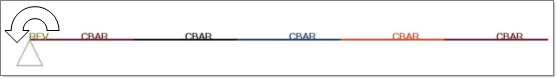
Rotating bar
The optimization problem is stated as:
Objective:
|
Minimize maximum normal stress.
|
Constraints:
|
Mass < 10kg.
|
Design variables:
|
Radius of each bar properties (PBARL).
|
In this tutorial, you will learn to:
| • | Setup an ESL MBD optimization problem in HyperMesh |
Exercise
Setting Up an ESL MBD Optimization Problem in HyperMesh
Step 1: Launch HyperMesh Desktop, Set the User Profile and Retrieve the File
| 1. | Launch HyperMesh Desktop. |
| 2. | Choose OptiStruct in the User Profiles dialog and click OK. |
| 3. | From the File menu on the toolbar, select Open > Model. |
| 4. | Select the rotating_bar_design.hm file you saved to your working directory from the optistruct.zip file. Refer to Accessing the Model Files. |
Step 2: Define Boundary Condition for Structural Analysis in ESL Optimization
Structural analysis and optimization of the flexible bodies of this model are performed in ESL optimization. Thus, the boundary condition for the flexible bodies needs to be defined.
| 1. | In the Model browser, right-click and select Create > Load Collector. |
| 2. | In the Name: field, enter BCforOpt. |
| 3. | From the Preferences menu, select Graphics. |
| 4. | Make sure the graphics subpanel is select. Check the box for coincident picking. |
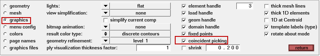
| 5. | Click return to go to main menu. |
| 6. | On the Model browser tab, select the display Properties view  . . |
| 7. | From the Analysis page, click constraints. |
Only 6 dof per flexible body should be fixed to remove 6 rigid body motion of each flexible body.
| 8. | From the graphics area, click the left end of the model. There should be two node numbers at one location. Select node number 1. |
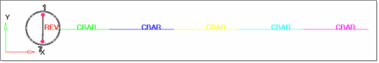
| 9. | Make sure all dofs (dof1 to dof6) are checked and their values are set to 0.00. |
Step 3: Define a Driving Motion Not Supported by HyperMesh
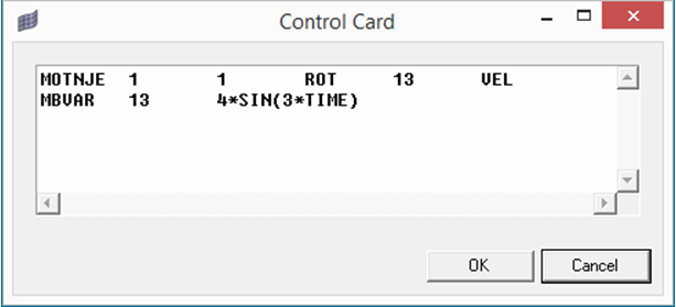
In this tutorial, the driving motion at a joint, MOTNJE is defined. However, MOTNJE is currently not supported by HyperMesh. Thus, you need to enter this card and a corresponding MBVAR card manually.
| 1. | From the Analysis page, select the control cards panel. |
| 2. | Click BULK_UNSUPPORTED_CARDS. |
| 3. | Make sure the following two cards are listed. If they are not listed, enter the cards. |
Step 4: Include Boundary Condition and MOTION in the Predefined MBD Subcase for Structural Analysis and Optimization
| 1. | Click on the load step SUBCASE1 in the Model browser. |
| 2. | In the Name field, enter Dynamic. |
| 3. | Make sure that the Analysis type is set to multi-body dynamics. |
| 4. | For SPC, select BCforOpt from the list of load collectors. |
| 5. | For MBSIM, select MBSIM1 from the list of load collectors. |
| 6. | For MOTION, select MBSIM1 from the list of load collectors. |
Step 5: Define the Size Design Variables for Optimization
| 1. | From the Analysis page, select the optimization panel. |
| 3. | Make sure that the desvar subpanel is selected using the radio buttons on the left-hand side of the panel. |
| 4. | Click desvar = and enter rad1. |
| 5. | Click initial value = and enter 10. |
| 6. | Click lower bound = and enter 0.05. |
| 7. | Click upper bound = and enter 100. |
| 8. | Set the move limit toggle to move limit default. |
| 9. | Set the discrete design variable (ddval) toggle to no ddval. |
| 10. | Click create. A design variable, 'rad1’, has been created. The design variable has an initial value of 10, a lower bound of 0.05, and an upper bound of 100. |
| 11. | Repeat steps 4 through 10 to create the design variable rad2, rad3, rad4, and rad5 using the same initial value, lower, and upper bounds. |
| 12. | Select the generic relationship subpanel using the radio buttons on the left-hand side of the panel. |
| 13. | Click name = and enter bar1_rad1. |
| 14. | Set the entity selection switch to prop. |
| 15. | Click prop and select PBARL_1 from the list. A property selection switch now appears below prop. |
| 16. | Make sure the property selection switch is set to Dimension 1. |
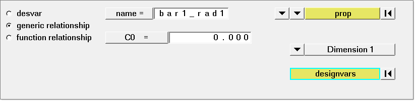
| 17. | Click designvars. The list of design variables appears. |
| 18. | Check the box next to rad1. |
Note the linear factor (value is box beside tube) automatically gets set to 1.000.
A design variable to property relationship, bar1_rad1, has been created relating the design variable rad1 to the radius entry on the PBARL card for property PBARL_1.
| 21. | Repeat steps 13 through 20 to create the design variable to property relationship bar2_rad2, bar3_rad3, bar4_rad4, and bar5_rad5 relating the design variables to the radius entry on the PBARL cards for the property PBARL_2, PBARL_3, PBARL_4, and PBARL_5. |
| 22. | Click return to go to the optimization panel. |
Step 6: Create the Mass and Stress Responses
A detailed description about the responses can be found in the OptiStruct User's Guide topic, Responses.
| 1. | Enter the responses panel. |
| 2. | Click response = and enter Mass. |
| 3. | Click the response type: switch and select mass from the pop-up menu. |
| 4. | Ensure the regional selection is set to total (this is the default). |
| 5. | Click create. A response, mass, is defined for the total mass of the model. |
| 6. | Click response = and enter Stress. |
| 7. | Click the response type: switch and select static stress from the pop-up menu. |
| 8. | Click the entity selection switch and choose props. |
| 9. | Click props and select all properties in the list. |
| 11. | Make sure that stress is normal stress and stress recovery point is set to all. |
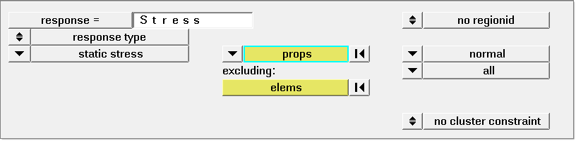
| 12. | Click create. A response, Stress for all the bar elements, is defined. |
| 13. | Click return to go to the optimization panel. |
Step 7: Create Constraints
Upper bound constraint is to be defined for the response Mass.
| 1. | Select the dconstraints panel. |
| 2. | Click constraint = and enter Mass. |
| 3. | Click response = and select Mass from the list of responses. |
| 4. | Check the box next to upper bound =. |
| 5. | Click upper bound = and enter 10.0. |
| 6. | Click create. A constraint is defined on the response Mass. The constraint is an upper bound with a value of 10.0. |
| 7. | Click return to go to the optimization panel. |
Step 8: Define the Objective Function
In this example, the objective is to minimize the maximum stress of the model while the model rotates.
| 1. | Select the obj reference panel. |
| 2. | Click dobjref = and enter MaxStress. |
| 3. | Click response = and select Stress. |
| 4. | Check the boxes next to neg reference = and pos references =. |
| 5. | Make sure the toggle switch is set to loadsteps. |
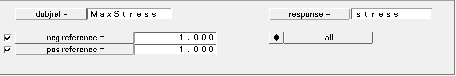
| 6. | Click loadsteps and select Dynamic. |
| 9. | Click return to go to the optimization panel. |
| 10. | Select the objective panel. |
| 11. | Click the switch in the upper left corner of the panel and select minmax from the pop-up menu. |
| 12. | Click dobjrefs = and select MaxStress. |
| 15. | Click return to go to the optimization panel. The objective function is now defined. |
Step 9: Save HyperMesh Database
| 1. | From the File menu, select Save as > Model. |
| 2. | Enter rotating_bar_design.hm in the file name field. |
Step 10: Launch OptiStruct
| 1. | From the Analysis page, select the OptiStruct panel. |
Notice the input file: field is populated with the same path you just saved the .hm file to with a new .fem extension.
| 2. | Set the export options: toggle to all. |
| 3. | Set the run options: toggle to optimization. |
| 4. | Set the memory options: toggle to memory default. |
| 5. | Click OptiStruct. This launches an OptiStruct run in a separate shell (DOS or UNIX) which appears. |
If the optimization was successful, no error messages are reported to the shell. The optimization is complete when the message Processing completed successfully appears in the shell.
If the job was successful, the new results file can be seen in the directory where the input file was saved. In addition to ordinary output files, you can see a text file with the name rotating_bar_design.eslout. This file is a good source to see the process of the ESL optimization.
After ~ 7 interations, the model should converge to the descending values as shown below:
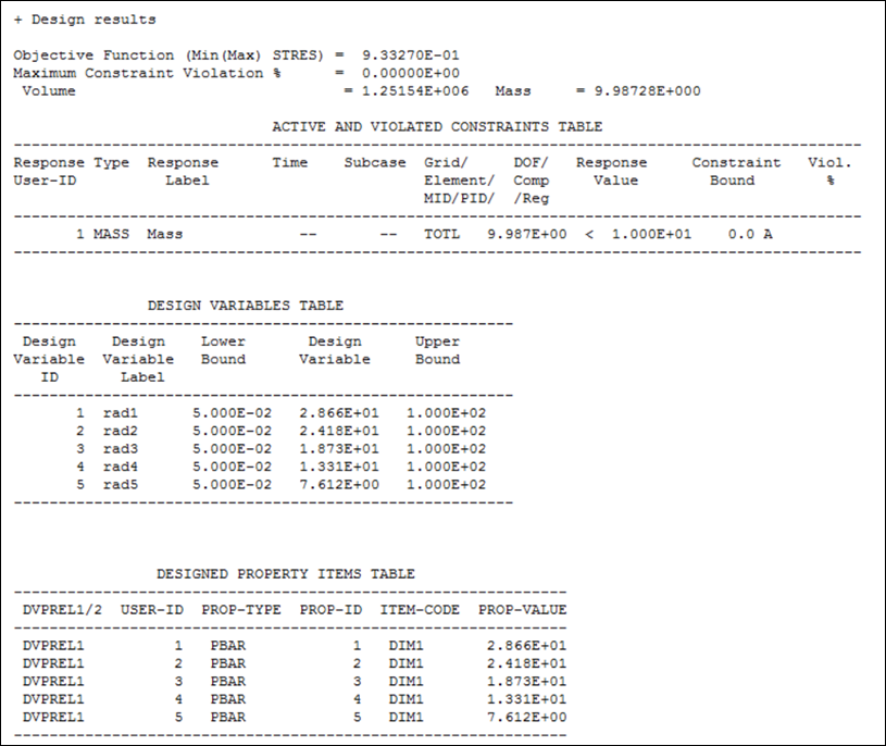
Optimization results (from rotating_bar_design.eslout).
See Also:
OptiStruct Tutorials


