How does MotionSolve and Simulink co-simulation work?
The following are the main points in creating and performing a co-simulation with Simulink:
| 1. | What form will the Simulink model take? (Simulink-driven vs. Simulink Coder Library): |
| a. | For a Simulink model (the Simulink model is exposed and you start co-simulation from within the Simulink interface): |
| • | S-Function represents the MotionSolve model: A Simulink model is connected to the MotionSolve model by creating an S-Function (System Function). An S-Function allows you to model any general system of equations with inputs, outputs, states, and so on, and is somewhat analogous to a Control_StateEqn in MotionSolve. The S-Function has the inputs and outputs connected from the rest of the Simulink model. |
| • | S-Function calls MotionSolve: Simulink calls MotionSolve via the same S-Function block from the previous step, which uses a library provided in the MotionSolve installation. (Note that environment variables must be set to run MotionSolve from Simulink). |
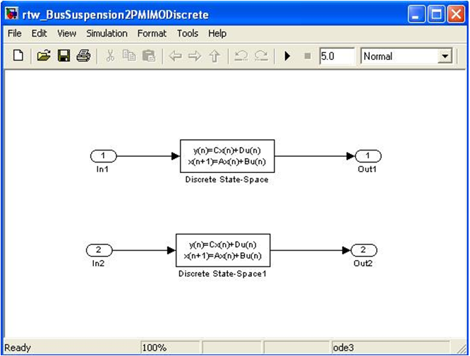
| b. | For a Simulink Coder (formerly Real-Time Workshop) generated model/library, co-sim driven by MotionSolve: |
| • | Simulink components Inports and Outports represent the interface to the MotionSolve model. For example, like the following (In1, In2, Out1, Out2 blocks): |
| 2. | Inputs/Outputs: The interface between two solvers is defined as the inputs and outputs from the systems to each other. Special modeling statements
(Control_PlantInput and Control_PlantOutput) are added to the MotionSolve model to specify the inputs/outputs to the MotionSolve model. These statements reference variables that are either used as inputs to the model (for example, forces or torques) or measure outputs (for example, displacements or velocities). |
| 3. | Communication Types: MotionSolve and Simulink models communicate data via a shared memory or TCP/IP. |
| 4. | Solver coordination: Solvers are held within one integration time step of each other to maintain accuracy. |
| 5. | Execution of solvers: MotionSolve and Simulink run in parallel, each on their own thread. Multi-threading gives superior performance to a single thread setup. |
| 6. | Input/output data interpolation/extrapolation: MotionSolve interpolates data in time as needed. You may choose zero-order, first-order, or second-order hold for data interpolation and extrapolation. |
| 7. | Output: Both solvers generate results for their respective models that can be post-processed within their own software. |
What are the software and hardware requirements to run a Simulink co-simulation?
Software requirements:
| • | Simulink Coder (formerly Real-Time Workshop), if generating a library |
Note that if generating a Simulink Coder library, this requires a supported compiler.
For details on supported versions, see the topic Supported Versions – Third Party Software in the XML Reference Guide.
See www.mathworks.com for supported version(s) of compilers for Simulink Coder, which should match the version of compilers supported by MotionSolve.
What do I need to do prior to running a Simulink-driven co-simulation with MotionSolve?
A few settings are needed to successfully run a co-simulation using MATLAB/Simulink. These steps can be performed in any order that is convenient. In other words, they don’t have any dependencies.
| 1. | In the MotionSolve model, create the plant inputs and outputs from the MotionSolve model to the other (for example, Simulink) model. |
| a. | The inputs should be applied using PINVAL() or VARVAL() (for example, to define forces from Simulink). |
| Note | The arguments that need to be specified for PINVAL() are different from the ones for VARVAL(). Please refer to the MotionSolve Reference Guide for details on the syntax. |
| b. | The outputs should use functions that provide values to Simulink (for example, DZ() for displacements) |
| 2. | In the environment that will run MATLAB/Simulink, set the environment variables needed by MotionSolve to be called from the other simulation software (for example, Simulink). |
| 3. | In MATLAB, set the search path for MATLAB/Simulink to find the S-Function library in the MotionSolve installation that is required for co-simulation. |
| 4. | In the Simulink model used for co-simulation, add an S-Function block that represents the MotionSolve model, and enter the proper arguments for the S-Function. |
Step 1: Plant Inputs and Plant Outputs.
Create one or more Control_PlantInput and Control_PlantOuput that stores a list of the input and output variables that are passed between MotionSolve and Simulink. For more details, see those statements in the XML Reference Guide and some of the other FAQ’s listed here.
The input variables from Control_PlantInput can be accessed via a PINVAL() or VARVAL() function, and the output variables from Control_PlantOutput are usually runtime functions (for example, DZ(), for displacement) going to Simulink.
Create the number Control_PlantInput’s and Control_PlantOutput’s in a manner that is convenient to you, and the S-Function that represents the MotionSolve model will update accordingly.
The order of the Control_PlantInput’s and Control_PlantOutput’s found in the MotionSolve model (.xml) (by line number, from top to bottom) should match the order of the inputs to and outputs from the S-Function.
Step 2: Setting up environment variables to run MotionSolve from MATLAB Simulink.
A few environment variables are needed for successfully running a co-simulation using MATLAB. These can be set using one of the following:
| • | In the shell/command window that calls MATLAB (for example, with the set command on Windows) |
| • | Within MATLAB, via the setenv() command |
| 1. | Set the environment variables to point to the solver binaries. |
NUSOL_DLL_DIR <installation directory>\hwsolvers\motionsolve\bin\<platform>
…where <installation directory> is the full path to the HyperWorks installation. <platform> is win32 for 32-bit Windows, win64 for 64-bit Windows, and so on.
For example, on Windows 64-bit:
set NUSOL_DLL_DIR=C:\Program Files\Altair\12.0\hwsolvers\motionsolve\bin\win64
| 2. | Set the environment variables for licensing: |
RADFLEX_PATH <installation directory>\hwsolvers\common\bin\<platform>
| PATH | <installation directory>\hwsolvers\common\bin\<platform>;%PATH% |
(Notice that the HyperWorks directory is pre-pended to the original PATH).
Note that other optional environment variables may be set for your model. See MotionSolve Environment Variables for more information on these environment variables.
Step 3: Setting the search path for MATLAB/Simulink.
The core feature in Simulink that creates the co-simulation is an S-Function (System Function) block in Simulink. This block requires an S-Function library (a dynamically loaded library) to define its behavior. MotionSolve provides this library, but the S-Function needs to be able to find it. To help MATLAB/Simulink find the S-Function, you need to add the location of the S-Function to the list of paths that MATLAB/Simulink uses in order to search for libraries.
The S-Function libraries for co-simulation with MotionSolve are called either:
mscosim – for SMP communication
mscosimipc – for IPC (TCP/IP sockets) communication
Changing the name of this library in the S-Function block in Simulink changes the communication behavior of the co-simulation.
These files are installed under <installation directory>\hwsolvers\motionsolve\bin\<platform>.
The location of these files needs to be added to the search path of MATLAB for the S-Function to use mscosim or mscosimipc.
This can be done in one of the following ways:
| a. | From the MATLAB menu, select File > Set Path… |
| b. | From the dialog box, add the directory where the mscosim and mscosimipc DLL’s reside. |
(for example, C:\Program Files\Altair\12.0\hwsolvers\motionsolve\bin\win64).
| c. | Select Save and Close. This procedure permanently adds this directory to the MATLAB/Simulink search path. |
At the MATLAB command line, type:
addpath(‘<installation directory>\hwsolvers\motionsolve\bin\<platform>’)
…to add the directory where the mscosim mex DLL resides into the MATLAB search path. It remains valid until you exit MATLAB. You can also create a .m script to make this process more easily repeatable.
For example, you can set the MATLAB Path and the necessary environment variables using MATLAB commands in a MATLAB (.m) script:
addpath('C:\Program Files\Altair\12.0\hwsolvers\motionsolve\bin\win64')
setenv('NUSOL_DLL_DIR','C:\Program Files\Altair\12.0\hwsolvers\motionsolve\bin\win64')
setenv('RADFLEX_PATH',['C:\Program Files\Altair\12.0\hwsolvers\common\bin\win64')
setenv('PATH',['C:\Program Files\Altair\12.0\hwsolvers\common\bin\win64;' getenv('PATH')])
Step 4: Add the S-Function block for Simulink that calls MotionSolve.
Add an S-Function block in your Simulink model. An S-Function (system-function) block can be found in the Simulink User-Defined Functions block library. An S-Function allows you to model any general system of equations with inputs, outputs, states, and so on, and is somewhat analogous to a Control_StateEqn in MotionSolve. See the MATLAB/Simulink documentation for more details.
After creating it, you will need to enter the arguments described in the next section.
For an example of this process, see the tutorial MV-7002.
What are the arguments that are required for the MotionSolve S-Function in Simulink?
For S-Function name: Enter one of the following:
mscosim (for SMP communication (Shared Memory))
mscosimipc (for IPC communication (Inter-Process Communication, via TCP/IP sockets))
For S-Function parameters: Enter these three required parameters and correspond to the following inputs to the MotionSolve library, mbd_d.exe:
| 1. | MotionSolve model name (.xml). |
| 2. | MotionSolve output name (.mrf). |
| 3. | MotionSolve user library name (.dll; if a user library is not used, enter empty quotes, ‘ ’, to signify this). |
S-Function modules: Does not need a parameter.
What do I need to do prior to running a Simulink Coder co-simulation with MotionSolve?
Simulink Coder may be used to generate a library that represents the Simulink model and runs with MotionSolve. The following provides the main steps involved. For complete details, see tutorial MV-7005.
Step 1: Plant Inputs and Plant Outputs.
Create one or more Control_PlantInput and Control_PlantOuput that stores a list of the input and output variables that are passed between MotionSolve and Simulink. For more details, see those statements in the XML Format Reference Guide and some of the other FAQ’s listed here.
The input variables from Control_PlantInput can be accessed via a PINVAL() or VARVAL() function, and the output variables from Control_PlantOutput are usually runtime functions (for example, DZ(), for displacement) going to Simulink.
Create the number Control_PlantInput’s and Control_PlantOutput’s as Inports and Outports, respectively, (for example, one Control_PlantInput for each Outport) in the Simulink model to setup the proper interface communication.
The order of the Control_PlantInput’s and Control_PlantOutput’s found in the MotionSolve model (.xml) (by line number, from top to bottom) should match the order of the ID's for the Outports and Inports, respectively, in the Simulink model to ensure the variables are exchanged in the proper order.
For a Simulink Coder library co-simulation, set usrsub_param_string to have one integer that will uniquely identify the Simulink Coder library used. This number (id) should be the same for all Control_PlantInput’s and Control_PlantOutput’s that are used for this Simulink Coder library.
Step 2: Simulink Inports and Outports
The next main step is to create or confirm that your Simulink model has Inports and Outports that match the corresponding Control_PlantOutput’s and Control_PlantIntput’s, respectively.
Step 3: Simulink Coder Setup
Simulink Coder configured and used to generate a set of source code in C++ that can be used to build a library in the next step.
Step 4: Build Simulink Library in Compiler
Finally, the source code is loaded into a compiler and modified. The compiler is configured and you can build the library. An installation of MATLAB and MotionSolve is needed to complete this process. After the library is generated, it no longer requires a license to use it.


