In this tutorial, you continue to gain an understanding of the basic concepts for creating a OptiStruct input file. More specifically, learn how to set up a model for modal analysis, specify solver specific controls and also submit an input file to the solver from HyperMesh.
Problem Statement
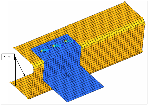
The channel_brkt_modal.hm file is used for this tutorial. It contains the bracket and channel assembly pictured below.
To complete the setup of the model for a modal analysis with OptiStruct, you need to define a normal modes SUBCASE, containing METHOD and SPC statements.

The following exercises are included:
| • | Create constraints (SPC) on the channel’s geometry lines, as shown in the image above. Then map the constraints to the channel nodes associated to the geometry lines. |
| • | Define a load step (OptiStruct loadsteps) |
Name the load step modal_run. For METHOD, point to the EIGRL card, and for SPC point to the constraints collector.
| • | Use OUTPUT on control cards panel to control the format of results output. |
Specify a h3d file as the output format. Add a second OUTPUT line and select the option HM for a HyperMesh .res file.
| • | Export the model to a OptiStruct input file |
Specify a filename with the extension *.fem.
| • | Submit the OptiStruct input file to OptiStruct |
Exercise
Step 1: Select User Profile and retrieve the HyperMesh model file
| 1. | Launch HyperMesh. The User Profiles dialogs appears. |
| 2. | Select OptiStruct and click OK. This loads the user profile. It includes the appropriate template, macro menu, and import reader, paring down the functionality of HyperMesh to what is relevant for generating models for OptiStruct. |
| 3. | Click File > Open. An Open Model browser window opens. |
| Note: | If HyperMesh Desktop was launched, use: File > Open > Model. |
|
| 4. | Select the channel_brkt_modal.hm file you saved to your working directory from the optistruct.zip file. Refer to Accessing the Model Files. |
Step 2: Review and edit the materials for this analysis
This step can be done from the Model browser.
| 1. | In the Model browser, expand the Material folder to show the two materials in the model. |
| 2. | Click on aluminum and the material entry is displayed in the Entity Editor. |
| 4. | Repeat steps 1 to 3 to input an RHO value of 7.9e-9 for the steel entry. |
Step 3: Create a load collector named modal
This can be done using the Load Collectors panel and the create subpanel. You need a card image for the EIGRL modal collector and no card image for the constraints collector.
| 1. | In the Model browser, right-click and select Create > Load Collector. |
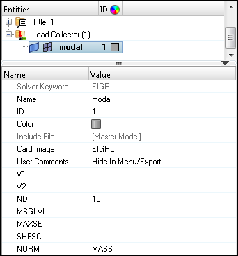
| 3. | For Card Image, select EIGRL. |
| 4. | For ND, enter 10. Here, ND specifies the number of modes that need to be extracted. |

Step 4: Create a load collector named constraints
| 1. | In the Model browser, right-click and select Create > Load Collector. |
| 2. | For Name, enter constraints. |
| 3. | Leave the Card Image set to None. |
Step 5: Apply constraints (OptiStruct SPC) on the channel
Display the geometry for the component channel and set the view to iso1. Then set the HyperMesh constraint configuration to SPC.
| 1. | Expand the Component folder in the Model browser. |
| 2. | Click the geometry icon  next to the channel component to turn the geometry display on. next to the channel component to turn the geometry display on. |
| 3. | Click the Isometric View icon  in the toolbar. in the toolbar. |
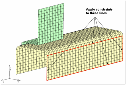
You are going to create the SPC constraints on the nodes along the lines on the perimeter of the channel’s bottom surface, as shown in the image below.

Apply constraints on the channel
| 4. | Click BCs > Create > Constraints to open the Constraints panel. |
| 5. | Switch the entity selector to lines. |
| 6. | Select the six lines on the perimeter of the channel’s bottom surface. |
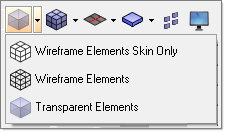
To view the selected lines clearly, switch to the Transparent Elements mode, as shown below:

| 7. | Activate degrees of freedom (dof) 1 through 6. |
For an OptiStruct linear static analysis, dof 1, 2, and 3 represent translations in the global x, y, and z directions respectively. Dof 4, 5, and 6 represent rotations about the global x, y and z axis, respectively.
| 8. | For size =, enter 10. The display size of the constraints is reduced. |
| 9. | Click create > return to exit the panel. |
Step 6: Map the constraints (OptiStruct SPC) on the geometry lines to the channel nodes associated to the lines
Use the load on geom panel in this step.
| 1. | From the Analysis page, click load on geom. |
| 2. | Click loadcols, and select constraints. |
| 3. | Click select to complete the selection of load collectors. |
| 4. | Click map loads. A constraint is at each node associated to the geometry lines. |
| 5. | Click return to exit the panel. |
Step 7: Define the load step (OptiStruct loadsteps) for the modal load case
Use the Load Step Entity Editor in this step. Define the loadstep to contain the load collectors constraints and modal.
| 1. | In the Model browser, right-click and select Create > Load Step. |
| 2. | For Name, enter normal_modes. |
| 3. | For Analysis type, select Normal modes. |
| 4. | For METHOD(STRUCT), select modal. |
| 5. | For SPC, select the load collector constraints. |
Step 8: Define the formats of result files to be output from OptiStruct
In the Control Cards panel, use the OUTPUT card to add two output requests for the Altair H3D and HyperMesh .res formats.
| 1. | Click Setup > Create > Control Cards to open the Control Cards panel. |
| 2. | Click next to go to the next panel menu of control cards. |
| 3. | Select the control card OUTPUT. |
Notice in the card image the one OUTPUT line is set to a default value. This specifies OptiStruct to output the results to a HyperMesh command file.
| 4. | Click the default value and select H3D from the pop-up menu. |
| 5. | For number_of_outputs =, enter 2. A second OUTPUT line appears in the card image. |
| 6. | Click the default value again and select HM for the second output type. |
This specifies OptiStruct to output results to a H3D file and a .res file, which can be viewed in HyperView Player. Also, an HTML report file is output and the H3D file is embedded in it.
| 7. | Click return to return to the Control Cards panel. |
Notice: The OUTPUT button is green. This indicates the card is exported to the OptiStruct input file.
| 8. | Click return to exit the panel. |
Step 9: Run the analysis and review the results
| 1. | From the Analysis page, click OptiStruct. |
| 2. | Click save as and enter the file name as modal_analysis.fem. |
| 3. | Click OptiStruct to submit the job. |
| 4. | Once the job has completed, the results can be reviewed in HyperView. |
See Also:
OptiStruct Tutorials


