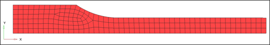
This tutorial demonstrates how to simulate a uniaxial tensile test using a quarter size mesh with symmetric boundary conditions.
The model is reduced to one-quarter of the total mesh with symmetric boundary conditions to simulate the presence of the rest of the part.
Model Description
| • | UNITS: Length (mm), Time (ms), Mass (kg), Force (kN) and Stress (GPa) |
| • | Simulation time Rootname_0000.rad [0 – 10.] |
| o | The 3 upper right nodes (TX, RY, and RZ) |
| o | The center node on left is totally fixed (TX, TY, Rx, RY, and RZ) |
| o | A symmetry boundary condition on all bottom nodes (TY, Rx, and RZ) |
| • | At the left side is applied a constant velocity = 1 mm/ms on -X direction. |
| • | Tensile test object dimensions = 11 x 100 with a uniform thickness = 1.7 mm |
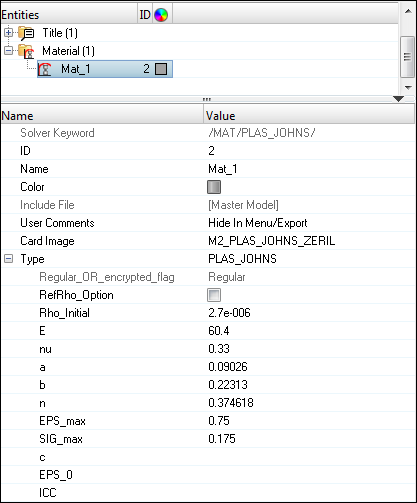
Johnson-Cook elastic plastic material /MAT/PLAS_JOHNS (Aluminum 6063 T7)
[Rho_I] Initial density = 2.7e-6 Kg/mm3
[E] Young’s modulus = 60.4 GPa
[nu] Poisson’s ratio = 0.33
[a] Yield Stress = 0.09026 GPa
[b] Hardening Parameter = 0.22313 GPa
[n] Hardening Exponent = 0.374618
[SIG_max] Maximum Stress = 0.175 GPa
[EPS_max] Failure Plastic Strain = 0.75
|
Input file for this tutorial: TENSILE_000.rad
Exercise
Step 1: Load the RADIOSS (Block) User Profile
| 1. | Launch HyperMesh Desktop. |
| 2. | From the Preferences menu, select the User Profiles or from the toolbar, click the  icon. icon. |
| 3. | Select RADIOSS (Block140) and click OK. |
Step 2: Load the solver deck
| 1. | Click File > Import > Solver Deck or click  . . |
| 2. | Click the Select File icon  to open the TENSILE_0000.rad file you saved to your working directory from the radioss.zip file. Refer to Accessing the Model Files. to open the TENSILE_0000.rad file you saved to your working directory from the radioss.zip file. Refer to Accessing the Model Files. |
| 5. | Click Close to close the window. |
Step 3: Define material for the tensile test object
| 1. | In the Model browser, right-click and select Create > Material. |
A Material with name material1 of card image M1_Elastic appears in the Entity Editor (EE) in the bottom pane of the Model browser.
| 2. | In the Entity Editor (EE), for Name, enter Mat_1 in the Value field. |
| 3. | Set Card Image to M2_PLAS_JOHNS_ZERIL. |
| 4. | Click Yes on the pop-up that warns of a card image change. |
| 5. | Input the values, as shown in the following image in the EE. |
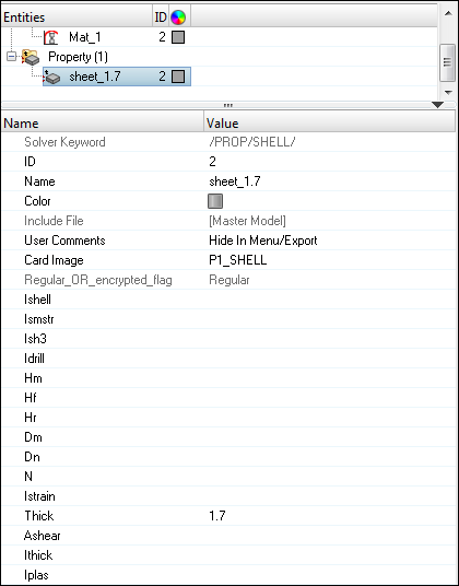
Step 4: Define property for the tensile test specimen
| 1. | In the Model browser, right-click and select Create > Property. |
A Property with name property1 of card image P1_SHELL appears in the Entity Editor (EE) in the bottom pane of the Model browser.
| 2. | For Name, enter sheet_1.7. |
| 3. | For Thick, enter 1.7. in the Value field corresponding to sheet thickness. |
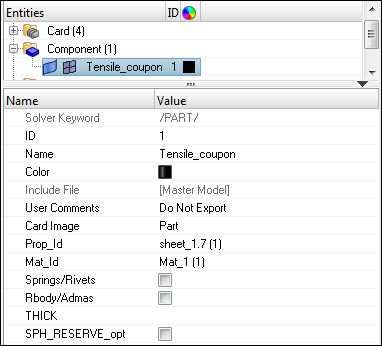
Step 5: Assign material and property to the test specimen
| 1. | In the Model browser, select the SHELL_1 component. The Entity Editor opens for the component. |
| 2. | For Name, enter Tensile_coupon. |
| 3. | Click Prop_Id, to activate the option. |
| 4. | Click Unspecified > Property. |
| 5. | In the Select Property dialog, select sheet_1.7 from the list and click OK. |
| 6. | Repeat steps 3 - 5 for Mat_Id and select Mat_1. |
Step 6: Create boundary conditions
| 1. | From the Utility browser, start the BCs Manager from the pull-down menu, select Tools > BCs Manager. |
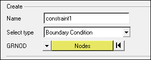
| 2. | For Name, enter constraint1, set Select type to Boundary Condition and set GRNOD to Nodes. |
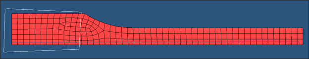
| 3. | Click on Nodes. A nodes selection appears. Select the three nodes, as shown in the figure below and click proceed. |
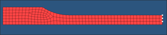
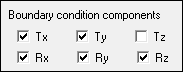
| 4. | Fix degrees of freedom Tx, Ry and Rz. |
| 5. | Click Create to create the constraint. The created constraint appears in the table, and handles appear in the graphics area. |
| 6. | For Name, enter constraint2, set Select type to Boundary Condition and set GRNOD to Nodes. |
| 7. | Select the node, as shown in the image below. |
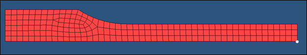
| 8. | Fix degrees of freedom Tx, Ty, Rx, Ry and Rz. |
| 9. | Click Create to create the constraint. The created constraint appears in the table, and a handle appears in the graphics area. |
| 10. | For Name, enter constraint3, set Select type to Boundary Condition and set GRNOD to Nodes. |
| 11. | Select the nodes, as shown in the image below. |
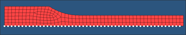
| 12. | Fix degrees of freedom Ty, Rx and Rz. |
| 13. | Click Create to create the constraint. The created constraint appears in the table, also handles appear in graphics. |
Step 7: Create Imposed Velocity
| 1. | For Name, enter velocity, set Select type as Imposed Velocity and set GRNOD to Nodes. |
| 2. | Select the nodes, as shown in the image below. |
| 3. | Set the direction as X and Scale Y as -1.0. |
| 4. | Click Create/Select curve ID for Curve ID. An XY curve editor appears. |
| 5. | Click New to create a new curve. |
| 6. | For Name, enter Load and click proceed. |
| 7. | Enter the values, as shown in table below. |
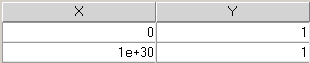
| 8. | Click Update to update the curve with the new values. |
| 9. | Click Close to close the Curve editor, the created curve is assigned to this constraint. |
| 10. | Click Create to create the velocity boundary condition. |
| 11. | Click Close to close the BCs Manager. |
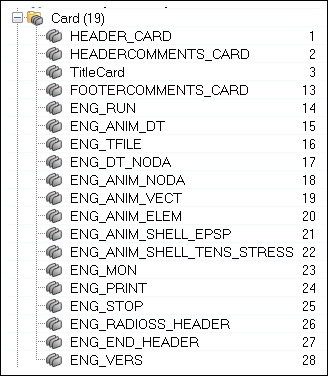
Step 8: Create output requests and control cards
For this exercise the output request will be generated from the Engine file assistant which is located in the Utility browser.
| 1. | To start the Engine file assistant, select Tools > Engine File Assistant. |
| 2. | Input the values, as shown below: |
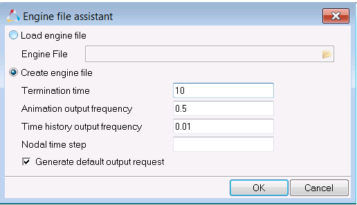
The tool generates typical output requests, such as stress, strain, velocity, etc.
Step 9: Export the model as TENSILE_0000.rad
| 1. | From the File menu, click Export > Solver Deck or click the Export Solver Deck icon  . . |
| 2. | For File:, click the folder icon and navigate to the destination directory where you want to export to. |
| 3. | Enter the name TENSILE_0000.rad and click Save. |
| 4. | Click the downward-pointing arrows next to Export options to expand the panel. |
| 5. | Select Merge starter and engine file to export the Engine and Starter file as one file. |

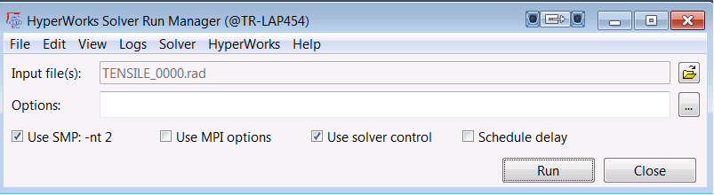
Step 10: Open RADIOSS Manager from Start menu
Step 11: Run the model TENSILE_0000.rad using RADIOSS Manager
| 1. | Select the TENSILE_0000.rad for the Input file. |
Step 12: Review the listing files for this run and verify the results
| 1. | See if there is any warning or errors on .out files. |
| 2. | Using HyperView, plot the displacement and strain contour. |
Exercise Expected Results
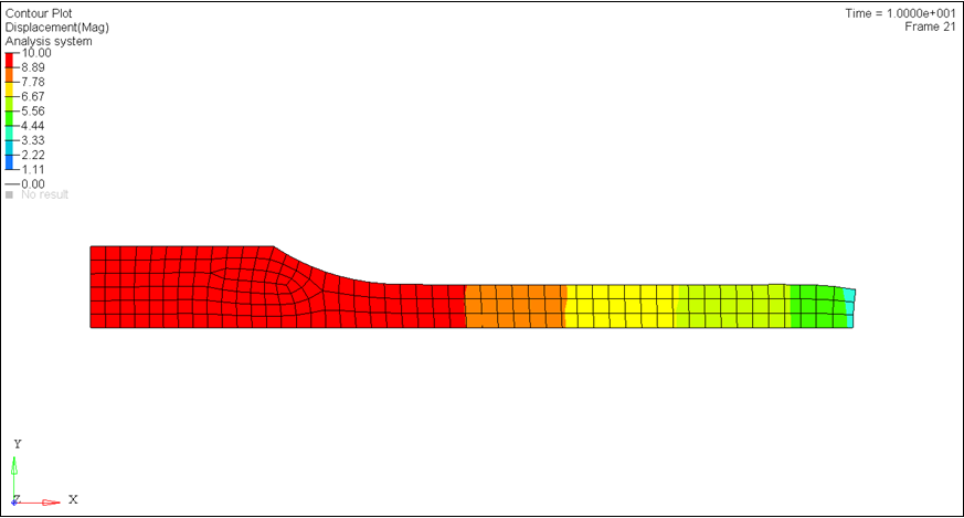
Total Displacement Contour (mm)
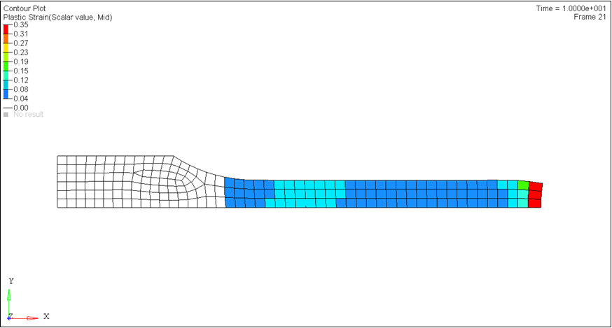
Plastic Strain Contour
See Also:
RADIOSS Tutorials
HyperStudy Tutorials


