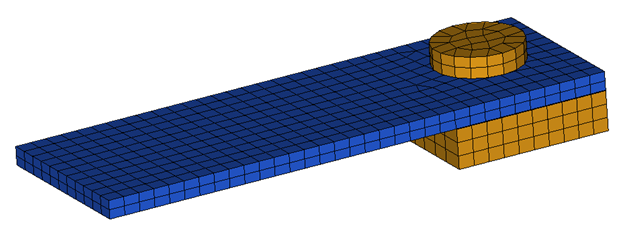
This tutorial demonstrates how to simulate a simple cantilever problem with a concentrated load at the free end, using Dynamic Relaxation (/DYREL) method to obtain a static solution.
Model Description
| • | UNITS: Length (mm), Time (ms), Mass (kg), Force (kN) and Stress (GPa) |
| o | CANTILEVER_0000.rad [0 – 25.1 ms] |
| • | Steps to setup this model: |
| o | Fix the Cantilever Beam to the support with a 10 kN pre-tension. The bolt attains 10 kN in 10 ms and remains constant thereafter. |
| o | After pre-tension, a concentrated load of 0.2 kN is gradually applied at the free end of the beam from 10 ms to 25 ms and it remains constant thereafter. |
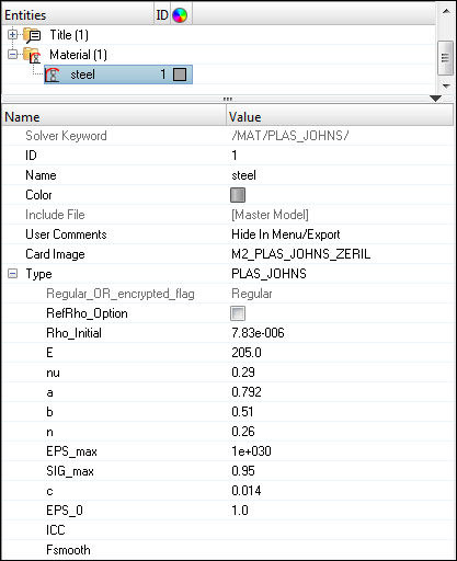
Elasto-plastic material /MAT/LAW2.
[Rho_I] Initial density = 7.83e-6 Kg/mm3
[E] Young’s modulus = 205 GPa
[nu] Poisson’s ratio = 0.29
[a] Yield Stress = 0.792 GPa
[b] Hardening Parameter = 0.510 GPa
[n] Hardening Exponent = 0.26
[SIG_max] Maximum Stress = 0.95 GPa
[c] Strain rate coefficient = 0.014 GPa
[EPS_0] Reference strain rate = 1
|
Input file for this tutorial: CANTILEVER_0000.rad
Exercise
Step 1: Load the RADIOSS (Block) User Profile
| 1. | Launch HyperMesh Desktop. |
| 2. | From the Preferences menu, select the User Profiles or from the toolbar, click the  icon. icon. |
| 3. | Select RADIOSS (Block140) and click OK. |
Step 2: Load the solver deck
| 1. | Click File > Import > Solver Deck or click  . . |
| 2. | Click the Select File icon  to open the CANTILEVER_0000.rad file you saved to your working directory from the radioss.zip file. Refer to Accessing the Model Files. to open the CANTILEVER_0000.rad file you saved to your working directory from the radioss.zip file. Refer to Accessing the Model Files. |
| 5. | Click Close to close the window. |
Step 3: Create a rigid body connecting spring ends to Bolt Support component
| 1. | In the Model browser, right-click and select Create > Component. |
A component is created and is shown in the Entity Editor (EE), below the Model browser.
| 2. | Using the Entity Editor (EE), change the Name to Rigids. |
| 3. | Set the Card Image as None. |
| 4. | In the Model browser, hide the component 1. |
| 5. | Click the Mask icon  in the toolbar. in the toolbar. |
| 6. | In the graphics area, select one element from the bolt. |
| 7. | Click on elems >> by attached to select the whole bolt. |
| 8. | Click mask to hide them and click return. |
| 9. | From the 1D page, select the rigids panel. |
| 10. | Click the selector arrow nodes 2-n: and change it to multiple nodes. |
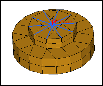
| 11. | In the rigids panel, for primary node, select the node at the end of spring, as shown in Fig 1 below, and for nodes 2-n, select the nodes, as shown in Fig 2. |
Note: Be sure to set the selector to multiple nodes.
Fig 1
Fig 2
| 12. | With all the DOF’s checked, click create to create the rigid body. |
| 13. | Click the Mask icon in the toolbar and click reverse to show remaining elements of the bolt. |
| 14. | Click return to exit the panel. |
| 15. | In the Model browser, rght-click the 3 components and click Show to display onscreen, as shown below. |
| 16. | Use Steps 3.10 through 3.12 to create a rigid body with the nodes shown in the following image with the other ends of the springs as the primary node and the nodes on the bolts as slave nodes. |
Step 4: Create and assign material, property to Plate and Support bolts
| 1. | In the Model browser, click the component 1. The component appears in the Entity Editor. |
| 2. | Change the name of the component to Plate. |
| 3. | Set Card Image to Part. |
| 4. | In the Model browser, right-click and select Create > Material. |
| 5. | For Name, enter Steel and set the Card Image to M2_PLAS_JOHNS_ZERIL and click Yes to confirm. |
| 6. | Enter the values, as shown below. |
| 7. | In the Model browser, right-click and select Create > Property. |
| 8. | For Name, enter Plate, and set the Card Image to P14_SOLID and click Yes to confirm. |
| 9. | In the Model browser, click the component 2, the EE for the component opens. |
| 10. | For Name, enter Bolt_Support. |
| 11. | Set the Card Image to Part. |
| 12. | For Prop_Id, click Unspecified > Property and select the property, Plate and click OK. |
| 13. | For Mat_Id , click Unspecified > Material and select the material, Steel and click OK. |
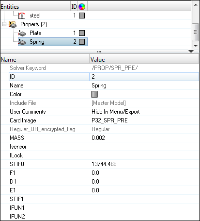
Step 5: Create and update properties for Pre-tensioner Spring
| 1. | In the Model browser, select the component 3, which opens the Entity Editor. |
| 2. | For Name, enter Spring. |
| 3. | Set the Card Image to Part. |
| 4. | In the Model browser, right-click and select Create > Property. A new property is created and a dialog opens with the new property. |
| 5. | Change the Name to Spring. |
| 6. | Set the Card Image to P32_SPR_PRE and click Yes to confirm. |
| 7. | Fill in the other values, as shown below: |
| 8. | In the Model browser, click on the property Spring to open the Entity Editor. |
| 9. | Right-click on IFUN2 and select Create to create and attach a curve. A Create Curve dialog opens. |
| 10. | Change the Name of the curve to Stiffness. |
| 11. | Click Close to exit the dialog. |
| 12. | In the Model browser, select the curve Stiffness, right-click and select Edit from context menu. |
| 13. | The XY curve editor appears. Fill in the values, as shown below. |
| 14. | Click Update > Close. The created curve is assigned to the property. |
Step 6: Defining Boundary Conditions to fix bottom of the BOLT_SUPPORT
| 1. | From the Tools menu, start the BCs Manager. |
| 2. | For Name, enter FIXED, set Select type to Boundary Condition and set GRNOD to Nodes. |
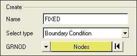
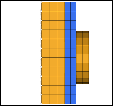
| 3. | Click on the nodes, the nodes selection appears; by window option, select the bottom layer of the bolt support, as shown below and the selection should appear as shown below in the XY Plane view: |
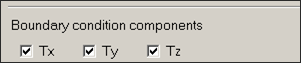
| 4. | Fix all translational degrees of freedom. |
| 5. | Click Create to create the constraint. The created constraint appears in the table and a handle appears in graphics area. |
Step 7: Defining the load (CLOAD) of the edge of the beam
| 1. | For Name, enter LOAD, set Select type to Concentrated Load and set GRNOD to Nodes. |
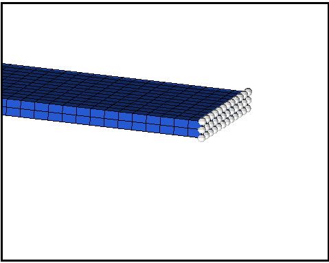
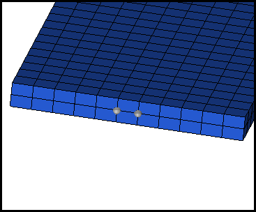
| 2. | Select the nodes on the edge of the beam, as shown in the image below by window option. |
| 3. | For Direction, select Y. |
| 4. | Set Scale Y, to -1.0 to apply load in negative Y direction. |
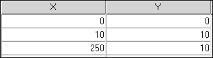
| 5. | Click the Create/Select curve tab. A GUI to enter curve appears. |
| 6. | Create a curve with Name LOAD and enter the values, as shown below using the same procedure explained in Step 5. |
x = {0, 10, 25, 250}
y = {0, 0, 0.02, 0.02}
| 7. | Click Update and Close in the XY curve editor GUI, the created curve is assigned to the BC. |
| 8. | Click Create to finish the creation of the load at the selected nodes. |
Step 8: Define a contact interface between Plate and Support_Bolt
| 1. | In the Model browser, right-click and select Create > Contact. A contact is created and the Entity Edit opens. |
| 3. | Set Card Image to TYPE7 and click Yes to confirm. |
| 4. | Click on Grnod_id (S) in the EE and set the selector to Components. |
| 5. | Pick the components Plate and Support_Bolt using the list selection dialog. |
| 6. | Click on Surf_id (M) in the EE and set the selector to Components. |
| 7. | Pick the components Plate and Support_Bolt using the list selection dialog. |
| 9. | For FRIC, enter 0.1 and for GAPmin, enter 0.04. |
Step 9: Create time history to obtain displacement at free end
| 1. | In Model browser, right-click and select Create > Output Block From the Analysis page, select the output block panel. |
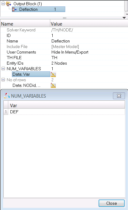
| 2. | In the Entity Editor, set the name to Deflection and select the nodes on the free end of the cantilever, as shown in the following image: |
| 3. | Set NUM_VARIABLES to 1 and click on the Data:Var icon  . A table will open, enter the variable name DEF. . A table will open, enter the variable name DEF. |
| 4. | Click edit and enter the variable name DEF. |
Step 10: Create output request and control cards
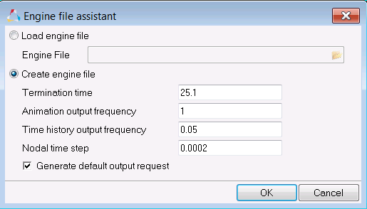
For this exercise the output request will be generated from the Engine file assistant which is located in the Utility browser.
| 1. | To start the Engine file assistant, select Tools > Engine File Assistant. |
| 2. | Input the values, as shown below: |
Step 11: Run the model checker
| 1. | Click Tools > Model Checker > RadiossBlock to open the Model Checker tab. |
| 2. | The Model Checker will display a list of perceived errors within the model. |
For most of these issues, the Model Checker is equipped to auto-correct many issues, decreasing the possibility of a solver error.
| 3. | Click the Apply Auto Correction icon  and click the Run icon and click the Run icon  to auto-correct issues within the model. to auto-correct issues within the model. |
Step 12: Export the model
| 1. | Click File > Export or click the Export icon  . . |
| 2. | For File:, click the folder icon  and navigate to the destination directory where you want to export to. and navigate to the destination directory where you want to export to. |
| 3. | For Name, enter CANTILEVER and click Save. |
| 4. | Click the downward-pointing arrows next to Export options to expand the panel. |
| 5. | Select Merge starter and engine file to export both the Starter and Engine file in one file. |
| 6. | Click Export to export the file. |
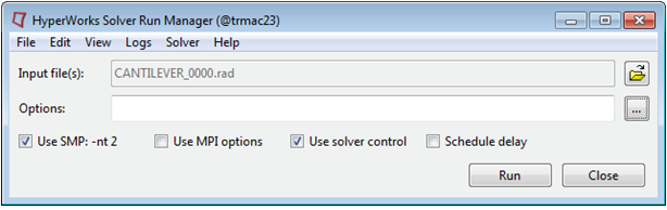
Step 13: Run the model in the solver
| 1. | Go to Start > Programs > Altair HyperWorks 2017 > RADIOSS. |
| 2. | For Input file, browse to the exercise folder and select the file CANTILEVER_0000.rad. |
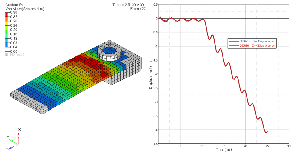
| 3. | Post-process the results with HyperView. |
| 4. | Using HyperGraph, open the T01 file and plot the deflection at the free end of the cantilever. |
See Also:
RADIOSS Tutorials


