For this tutorial it is recommended to complete the introductory tutorial, HM-1000: Getting Started with HyperMesh. Working knowledge of the creation and editing of collectors and card images are a definite pre-requisite. Familiarity with the Interfaces panel, and the creation of boundary conditions are useful, although not required.
Objective
In this tutorial you will learn how to set up a RADIOSS input file in HyperMesh for analyzing the impact response between two pipes. The modeling steps that are covered are:
| • | Creating materials, sections, and parts for the model. |
| • | Defining the contact between the two pipes using /INTER/TYPE7. |
| • | Applying a translational initial velocity to a pipe using the /INIVEL card. |
| • | Applying local constraints to the other pipe using the /BCS card. |
Model Description
The units used in this tutorial are milliseconds, millimeters and kilograms (ms, mm, kg), and the tutorial is based on RADIOSS 14.0.
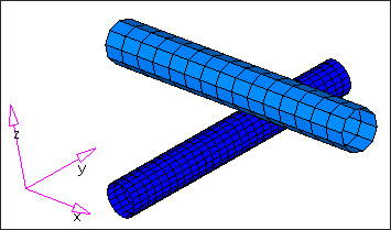
Pipe model
Exercise
Step 1: Load the RADIOSS (Block) User Profile
| 1. | Launch HyperMesh Desktop. |
| 2. | From the Preferences menu, select the User Profiles or click the  icon on the toolbar. icon on the toolbar. |
| 3. | Select RADIOSS (Block140) and click OK. |
Step 2: Import the solver deck
| 1. | Click File > Import > Solver Deck or click  . . |
| 2. | Click the Select File icon  to open the pipesd00.rad file you saved to your working directory from the radioss.zip file. Refer to Accessing the Model Files. to open the pipesd00.rad file you saved to your working directory from the radioss.zip file. Refer to Accessing the Model Files. |
| 3. | Click Import. The model loads into the graphics area. |
| Note: | On import of a RADIOSS deck, any HyperMesh warning and error messages are written to a file named radiossblk.msg. This file is created in the folder from which HyperMesh is started. The content of the file is also displayed in a pop-up window. |
On import, any RADIOSS cards not supported by HyperMesh are written to the control card unsupp_cards. This card is accessed from the control cards panel on the BCs page and is a pop-up text editor. The unsupported cards are exported with the rest of the model.
Care should be taken if an unsupported card points to an entity in HyperMesh. An example of this is an unsupported material referenced by a /PART card. HyperMesh stores unsupported cards as text and does not consider pointers.
On import, HyperMesh renumbers entities having the same ID as other entities. In HyperMesh, for example, all elements must have a unique ID. The message file radiossblk.msg provides a list of renumbered elements and their original and new IDs.
|
Step 3: Understand the relationships between the /PART, /SHELL, /MAT and /PROP cards in HyperMesh
A /PART shares attributes such as section properties (/PROP) and a material (/MAT). A group of shells (/SHELL) sharing common attributes generally share a common part ID (PID).
The figure below shows how these keywords are mapped to HyperMesh entities:
/SHELL
|
elem_ID
|
part_ID
|

|
Organized into component collectors
|
|
|
|
/PART
|
part_ID
|
prop_ID
|
mat_ID
|
|
Component collector with a component card image
|
|
|
|
/PROP
|
prop_ID
|
|
Property collector with a property card image
|
|
|
|
/MAT
|
mat_ID
|
|
Material collector with a material card image
|
Map to HyperMesh Entities
Component, property and material collectors are created and edited from the Collectors panel.
For the RADIOSS keyword interface, there is only one component card image and it is named Part. There are several property card images, such as P1_SHELL, P2_TRUSS, and P14_SOLID. There are many material card images, such as M1_ELAST and M48_HONEYCOMB.
The complete list of card images is available from the Collectors panel, as you assign card images to the various types of collectors.
A HyperMesh card image allows you to view the image of keywords and data lines for defined RADIOSS entities as interpreted by the loaded template. The keywords and data lines appear in the exported RADIOSS input file as you see them in the card images. Additionally, for some card images, you can define and edit various parameters and data items for the corresponding RADIOSS.
Use the Entity Editor or card (card editor) panel from the permanent menu to review and edit card images. Also, for many entities, their card image can be viewed and edited from the panels in which they are created.
Step 4: Create a /MAT card
In HyperMesh, a /MAT card is associated to a material collector. To relate it to a /PART card, the material needs to be assigned to a component.
You can assign the material to the component collector as you create the component using the Create subpanel of the Collectors panel or from component create options in the pull-downs or from the Model browser using the Entity Editor (EE). In situations where the material was not assigned to the component at the time of creation (and in this case, a dummy material is created with the same name as the component collector), update the component collector's definition by assigning the material in the Update subpanel of the Collectors panel or from the Assign option in Model browser or using the Entity Editor (EE) of the component.
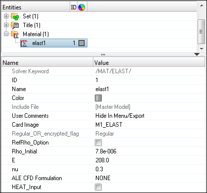
In this step, create a material with the M1_ELAST card image using the Model browser. This material will be assigned to both pipes.
| 1. | In the Model browser, right-click and select Create > Material. A material is created and displayed in the Entity Editor (EE) below the Model browser. |
| 2. | For Name, enter elast1. |
| 3. | Set Card Image to M1_ELAST. |
| 4. | In the Entity Editor (EE), click to activate the field. |
Rho_Initial (density), enter 7.8E-6
E (Young's modulus), enter 208
nu (Poisson's ratio), enter 0.30
| Note: | If you have difficulties completing any task with the creation, update or editing of materials in this tutorial, refer to the on-line help for the materials by clicking Help from the menu. |
|
| Hint: | Any material that was mistakenly created with wrong values can be edited using the card image option. |
|
In this step, the material created will be used for the analysis. The next step is to define the /PROP card that will be used to define the properties of the elements in the model.
Step 5: Create a /PROP card
In HyperMesh, the /PROP card is assigned to a property. To generate this card, create a property collector using either the Property icon  in the toolbar or click Properties > Create from the pull-down or from the Model browser, click Create > Property.
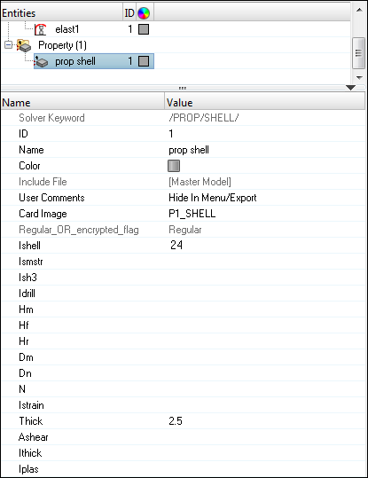
The model consists of two pipes modeled with shell elements. Create a property with a /PROP/SHELL card that will be used for all the elements.
| 1. | In the Model browser, right-click and select Create > Property. A property is created and displayed in the Entity Editor (EE). |
| 2. | For Name, enter prop_shell. |
| 3. | Set Card Image to P1_SHELL. |
| 5. | For shell thickness Thick, enter 2.5. |
Step 6: Assign the /PART, /MAT and /PROP cards to the elements
Assign the /PART card to the component for the coarse pipe and specify the /PROP/SHELL card ID in it.
| 1. | In the Model browser, select the components Pipe1 and Pipe2. A combined Entity Editor (EE) appears for both the selected components. |
| 2. | Set Card Image to PART. |
| 3. | For Prop_Id, click Unspecified > Property and select the property, prop shell and click OK. |
| 4. | For Mat_Id, click Unspecified > Material and select the material, elast1 and click OK. |
Step 7: Create Interface/Contact cards
RADIOSS contacts can be created from Model browser, with a right-click Create > Contact, they can also be created in the Interfaces panel from the Analysis page or from the menu, select BCs > Create > Interfaces.
A RADIOSS contact is a HyperMesh group. When you want to manipulate an /INTER card, such as delete it, renumber it, or turn it off, you need to work with HyperMesh group entities.
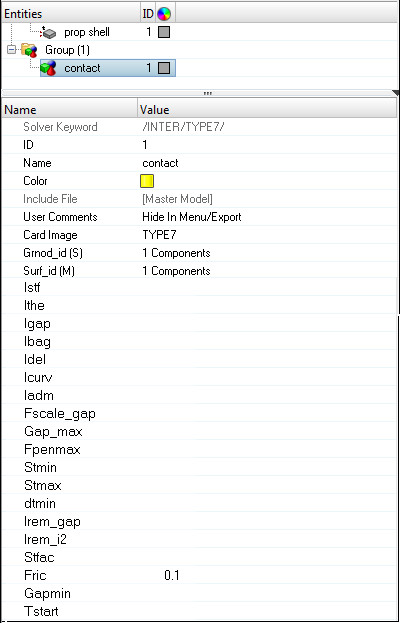
In this step, create a contact between the two pipes using /INTER/TYPE7. The pipe with the coarser mesh (2) will be the master surface while the one with finer mesh (1) will be the slave surface. RADIOSS has multiple ways to define master and slave entity types from which to choose; in this example define the master and slave entities as components, by doing this, the master will be exported as /SURF/PART and the slave as a /GRNOD/PART.
| 1. | In the Model browser, right-click and select Create > Contact. A contact is created and the Entity Editor (EE) opens. |
| 2. | For Name field, enter contact. |
| 3. | Set Card Image to TYPE7 and click Yes to confirm. |
| 4. | For Surf_id(M) that corresponds to the master selection, click on the drop-down arrow and select Components. |
| 5. | Click Components and select component 2 in the selection or on the graphics window and click OK. |
| 6. | For Grnod_id(S) that corresponds to the slave selection, click on the drop-down arrow and select Components. |
| 7. | Click Components and select component 1 in the selection or on the graphics window and click OK. |
| 8. | For static coefficient [Fric], enter 0.10. |
In this step, you defined the contact between the two pipes as /INTER/TYPE7.
Step 8: Create boundary conditions
Boundary conditions for RADIOSS can be efficiently created using the BC’s Manager available on the Utility browser. The BC’s Manager can be accessed from the Tools menu. RADIOSS boundary conditions are mapped to load collector in HyperMesh.
In this step, you will apply a translational initial velocity along Z direction to the coarse pipe using BC’s Manager.
| 1. | In the BCs Manager, enter Name as tran_vel and set Select type as Initial Velocity under the Create header. |
| 2. | Click Parts, select component 2 from the GUI, and click proceed. This creates the entity set of type GRNOD, which is referred to in the /INIVEL card. |
| 3. | In the BC’s Manager, enter the initial velocity components as 0, 0 and -30 for Vx, Vy and Vz fields. |
There is an option for creating/referring the initial velocity card to a local coordinate system. However, if nothing is specified, the global coordinate system is selected by default.
| 4. | Click Create. Cross check in the Model browser for your reference that a load collector and an entity set are created. |
This completes the creation of an initial velocity for the pipe in the negative global Z direction.
Step 9: Create a /BCS and constrain the finer mesh pipe
In this step, you will fully constrain the end nodes of the bottom pipe by using the Boundary Conditions Manager.
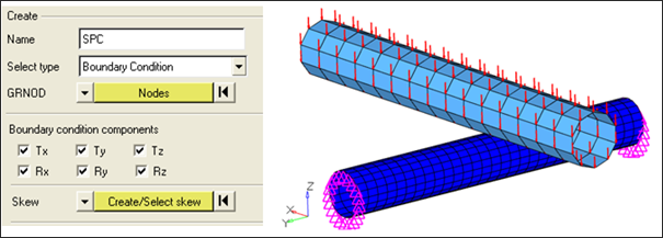
| 1. | In the BCs Manager, enter Name as SPC and set Select type as Boundary Condition. |
| 2. | Now specify the node set of type as GRNOD for the BCS card, switch the entity from Parts to Nodes and select the end nodes of the bottom pipe, which are to be constrained. |
| 3. | Under the Boundary condition components subheading (as illustrated below) activate all the translational and rotational check boxes. Click Create. |
A load collector with a BCS card is created and applied the nodes as selected in the above steps. A corresponding node set is created.
Step 10: Create output definitions and control cards
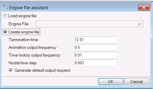
For this exercise the output request will be generated from the Engine file assistant which is located in the Utility browser.
| 1. | To start the Engine file assistant, select Tools > Engine File Assistant. |
| 2. | Input the values, as shown below: |
Step 11: Export the model
| 1. | Click File > Export or click the Export icon  . . |
| 2. | For File:, click the folder icon  and then navigate to the destination directory where you want to export to. and then navigate to the destination directory where you want to export to. |
| 3. | For Name, enter pipe and click Save. |
| 4. | Click the downward-pointing arrows next to Export options to expand the panel. |
| 5. | Select Merge starter and engine file to export both the Starter and Engine file in one file. |
| 6. | Click Export to export the solver deck. |
This concludes this tutorial. You may discard this HyperMesh model or save it for your own reference.
In this tutorial some of the concepts that govern the HyperMesh interface to RADIOSS are introduced. You also used numerous panels that allowed you to do basic modeling in terms of RADIOSS, such as defining contacts or boundary conditions.
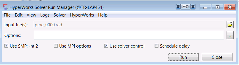
Step 12: Run the model in the solver
| 1. | Go to Start > Programs > Altair HyperWorks 14.0 > RADIOSS. |
| 2. | For Input file, browse to the exercise folder and select the file pipe_0000.rad. |
Exercise Expected Results
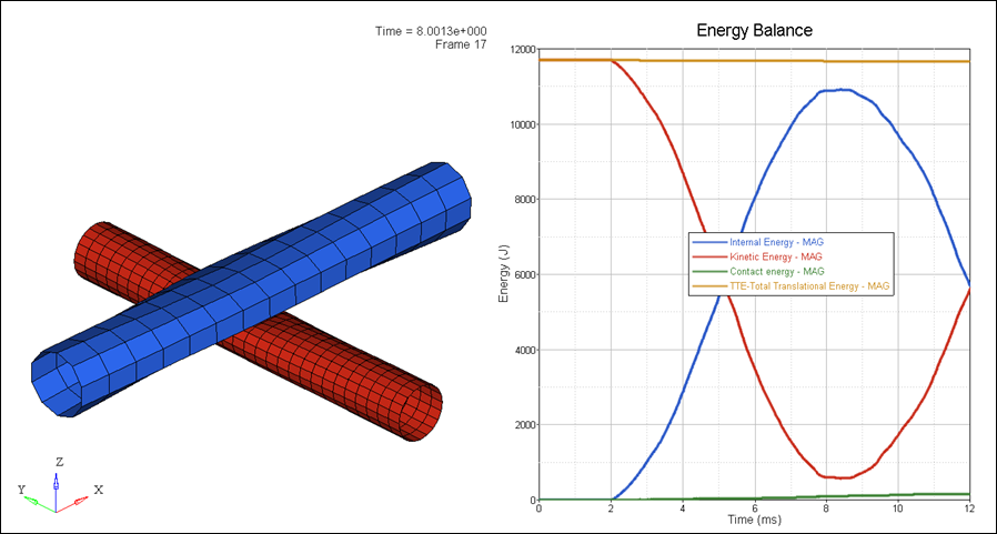
Deformation and energy balance plot
See Also:
See HyperMesh Tutorials for a complete list of tutorials.


