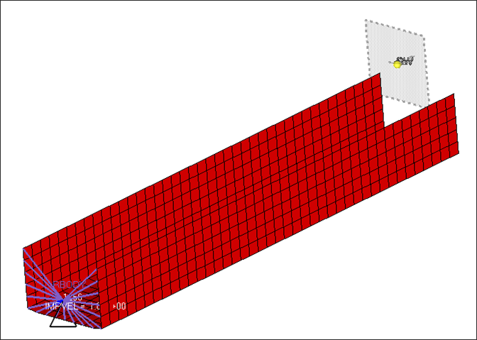
This exercise simulates buckling of a tube using half tube mesh with symmetric boundary conditions.
The figure illustrates the structural model used for this tutorial: a half tube with a rectangular section (38.1 x 25.4 mm) and length of 203 mm.
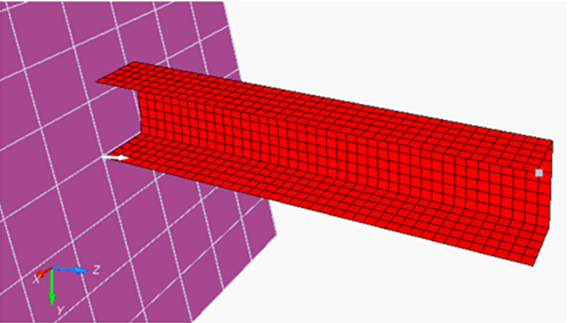
Model Description
| • | UNITS: Length (mm), Time (ms), Mass (kg), Force (kN) and Stress (GPa) |
| • | Simulation time: Engine [0 – 10 ms] |
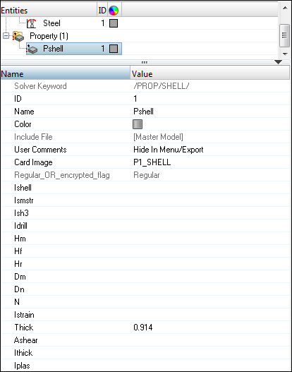
| • | The tube thickness is 0.914 mm. |
| • | An imposed velocity of 13.3 mm/ms (~30 MPH) is applied to the right end of the tube |
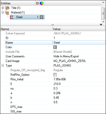
| • | Elasto-plastic material using Johnson-Cook law /MAT/PLAS_JOHNS (STEEL). |
[Rho_Initial] Initial density = 7.85e-6 Kg/mm3
|
[E] Young’s modulus = 210 GPa
|
[nu] Poisson coefficient = 0.33
|
[a] Yield Stress = 0.206 GPa
|
[b] Hardening Parameter = 0.450 GPa
|
[n] Hardening Exponent = 0.5
|
[SIG_max] Maximum Stress = 0.0 GPa
|
File needed to complete this tutorial: tube_box.hm
Exercise
Step 1: Load the RADIOSS User Profile
| 1. | Launch HyperMesh Desktop. |
| 2. | From the Preferences menu, select the User Profiles or click the  icon on the toolbar. icon on the toolbar. |
| 3. | Select RADIOSS (Block140) and click OK. |
Step 2: Load the model
| 1. | From the toolbar, click the Open Model icon  to open the tube_box.hm file you saved to your working directory from the radioss.zip file. Refer to Accessing the Model Files. to open the tube_box.hm file you saved to your working directory from the radioss.zip file. Refer to Accessing the Model Files. |
| 2. | Click Open. The model loads into the graphics area. |
Step 3: Create Material for the tube
| 1. | In the Model browser, right-click and select Create > Material. The Entity Editor is displayed below the Model browser. |
| 3. | Set Card Image to M2_PLAS_JOHNS_ZERIL and click Yes to confirm. |
| 4. | Set Type as PLAS_JOHNS. |
| 5. | Input the values, as shown below: |
| 6. | Click anywhere in the Model browser to exit the Entity Editor. |
Step 4: Create Property for the tube
| 1. | In the Model browser, right-click and select Create > Property. The Entity Editor is displayed below the Model browser. |
| 2. | For Name, enter Pshell. |
| 3. | Set Card Image to P1_SHELL. |
| 4. | Input the values, as shown below: |
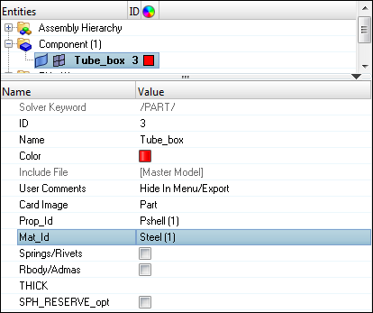
Step 5: Assign material and property to the component
| 1. | Select the component Tube_box in the Model browser. |
| 2. | In the Entity Editor, for Prop_Id, click Unspecified > Property |
| 3. | In the Select Property dialog, select Pshell and click OK. |
| 4. | In the Entity Editor, for Mat_Id, click Unspecified > Material. |
| 5. | In the Select Material dialog, select Steel and click OK. |
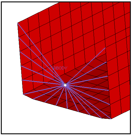
Step 6: Create Rigid Body
| 1. | Create a component collector RBODY. Set Card Image to None in the Entity Editor. |
| 2. | In the 1D page, select rigids. |
| 3. | Set nodes 2-n to multiple nodes. |
| 4. | Set primary node tab to calculate node. |
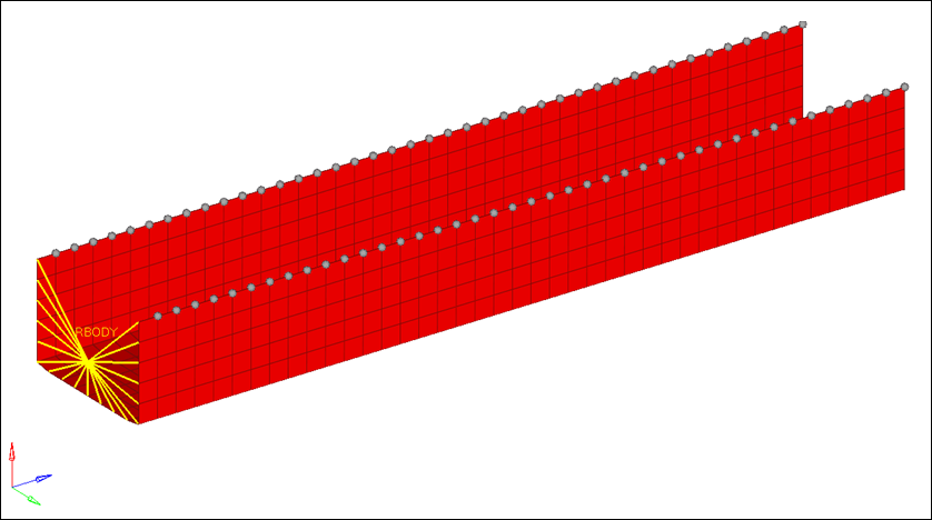
| 5. | Select the nodes of one edge to tie all the degree’s of freedom, as shown in the image below: |
Step 7: Create Symmetry Boundary Conditions
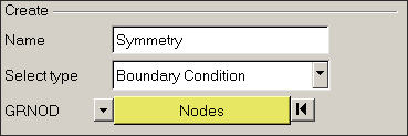
| 1. | Click Tools > BCs Manager to start the BCs Manager. |
| 2. | For Name, enter Symmetry, set Select type as Boundary Condition and set GRNOD to Nodes. |
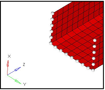
| 3. | Click on the nodes, nodes selection appears; by window option, select the top layer of the channel as shown below and the selection should appear as below: |
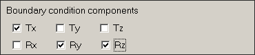
| 4. | Fix the degrees of freedom for symmetry condition, as shown below: |
| 5. | Click Create to create the constraint. The created constraint appears in the table, and a handle appears in graphics area. |
Step 8: Create Imposed Velocity
| 1. | For Name, enter Velocity, set Select type as Imposed Velocity and set GRNOD to Nodes. |
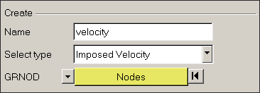
| 2. | Select the master node of the RBODY on which the boundary condition needs to be applied. |
| 3. | Set the Direction as Z. |
| 4. | Click Create/Select curve to create imposed velocity loading curve. A new GUI opens. |
| 5. | Click New to enter Load as the name of the curve. |
| 7. | Enter the X values as 0, 1000. |
| 8. | Enter corresponding Y values as 13.3, 13.3. |
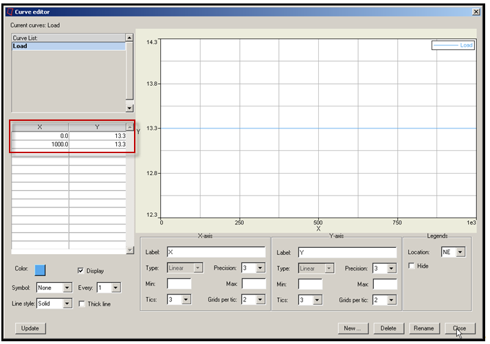
| 9. | Click the Create tab to create the constraint. The created constraint appears in the table and a handle appears in graphics area. |
Step 9: Create boundary condition on the rigid body
| 1. | Enter Name as RBODY_constraint, set Select type as Boundary Condition and set the GRNOD to Nodes. |
| 2. | Select the master node of the RBODY on which the boundary condition need to be applied. |
| 3. | Set the degrees of freedom to not allow movement in X and Y direction and no rotation about Y-axis and Z-axis, as shown below. |
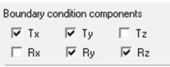
| 4. | Click the Create tab to create the constraint. The created constraint appears in the table and a handle appears in graphics area. |
Step 10: Create a Rigid Wall
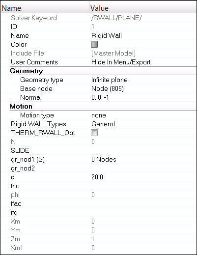
| 1. | In the Model browser, right-click and select Create > Rigid Wall. |
| 2. | Set the Geometry Type as Infinite plane. |
| 3. | Click on the Base node option and select extreme node opposite to rigid body edge. |
| 4. | Set the normal vector using the N1, N2, N3 option, as shown below. Ensure that N3 is not active. Click Proceed. |
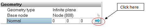
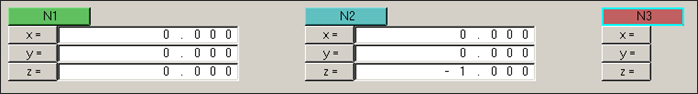
Note: Keep N3 inactive.
| 5. | Set d (distance) value to 20. |
| 6. | Go to Analysis > rigid walls panel. |
| 7. | Move to the Geometry page. Click on the Edit tab besides base node and change the Z value to 10.0 to be away from the channel along the Z-axis. |
Step 11: Creating a Self Contact to avoid self penetration during impact
| 1. | In the Model browser, right-click and select Create > Contact. The Entity Editor will open. |
| 2. | Enter the Name as Self_Interface and set the Card Image as TYPE7 and click Yes to confirm. |
| 3. | Toggle the option to Components for Grnod_id (S) (slave entity), select Tube_box and click OK. |
| 4. | Toggle the option to Components for Surf_id (M) (master entity), select Tube_box and click OK. |
| 5. | Set STFAC = 1, FRIC = 0.20 and GAPmin = 0.90. |
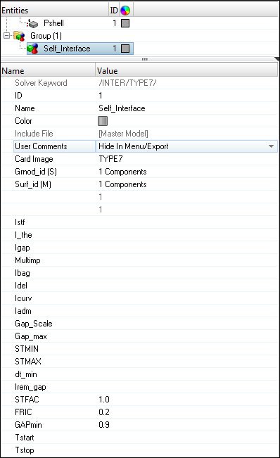
| 6. | Click anywhere in the Model browser to exit the Entity Editor. |
| 7. | To review the created interface, go to the Analysis > Interface panel. |
| 8. | Go to the update subpanel, select created interface and click review. It will show master and slave surface as blue and red. |
Step 12: Create output requests and control cards
| 1. | Launch the HyperMesh Solver browser from View > Browsers > HyperMesh > Solver. |
| 2. | Right-click in the Solver browser general area to create the cards, shown below with the given values for each parameter: |
Keyword Type
|
Keyword
|
Parameter
|
Parameter Value
|
CONTROL CARDS
|
TITLE
|
Status
|
[Checked]
|
CONTROL CARDS
|
TITLE
|
TITLE
|
Box_Tube
|
ENGINE KEYWORDS
|
RUN
|
Status
|
[Checked]
|
ENGINE KEYWORDS
|
RUN
|
Tstop
|
10.01
|
ENGINE KEYWORDS
|
PRINT
|
Status
|
[Checked]
|
ENGINE KEYWORDS
|
PRINT
|
N_Print
|
-100
|
ENGINE KEYWORDS
|
ANIM/ELEM
|
Status
|
[Checked]
|
ENGINE KEYWORDS
|
ANIM/ELEM
|
EPSP
|
[Checked]
|
ENGINE KEYWORDS
|
ANIM/ELEM
|
ENERGY
|
[Checked]
|
ENGINE KEYWORDS
|
ANIM/ELEM
|
VONM
|
[Checked]
|
ENGINE KEYWORDS
|
ANIM/ELEM
|
HOURG
|
[Checked]
|
ENGINE KEYWORDS
|
ANIM/VECT
|
Status
|
[Checked]
|
ENGINE KEYWORDS
|
ANIM/VECT
|
VEL
|
[Checked]
|
ENGINE KEYWORDS
|
ANIM/VECT
|
FOPT
|
[Checked]
|
ENGINE KEYWORDS
|
ANIM/VECT
|
CONT
|
[Checked]
|
ENGINE KEYWORDS
|
ANIM/DT
|
Status
|
[Checked]
|
ENGINE KEYWORDS
|
ANIM/DT
|
Tstart
|
0
|
ENGINE KEYWORDS
|
ANIM/DT
|
Tfreq
|
1
|
ENGINE KEYWORDS
|
ANIM/NODA
|
Status
|
[Checked]
|
ENGINE KEYWORDS
|
ANIM/NODA
|
DMAS
|
[Checked]
|
Step 13: Export the model
| 1. | Click File > Export or click the Export icon  . . |
| 2. | For File:, click the folder icon  and navigate to the destination directory where you want to export to. and navigate to the destination directory where you want to export to. |
| 3. | Enter the name boxtube and click Save. |
| 4. | Click the downward-pointing arrows next to Export options to expand the panel. |
| 5. | Select Merge starter and engine file to export the engine file with the model file. |
| 6. | Click Export to export the file. |
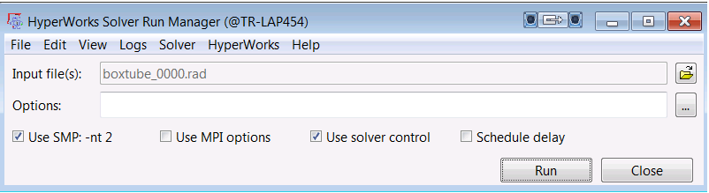
Step 14: Run the solver using RADIOSS Manager
| 1. | Go to Start > Programs > Altair HyperWorks 14.0 > RADIOSS. |
| 2. | For Input file, browse to the exercise folder and select the file boxtube_0000.rad. |
Step 15: Results analysis in HyperView
Exercise Expected Results
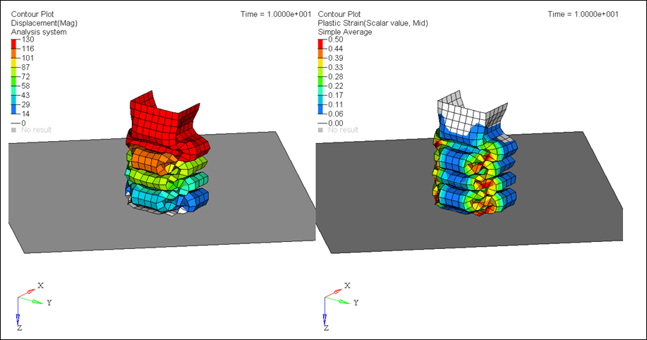
Total Displacement (mm) and Plastic Strain (Mid Layer, Simple Average)
See Also:
RADIOSS Tutorials


