RD-3540: Front Impact Bumper Model using HyperMesh |

|

|

|

|
|
RD-3540: Front Impact Bumper Model using HyperMesh |

|

|

|

|
RD-3540: Front Impact Bumper Model using HyperMesh |

|

|

|

|
|
RD-3540: Front Impact Bumper Model using HyperMesh |

|

|

|

|
For this tutorial it is recommended to complete the introductory tutorial HM-1000: Getting Started with HyperMesh, as well as RD-3520: Pre-Processing for Pipes Impact Using RADIOSS for the basic concepts on the HyperMesh RADIOSS interface.
In this tutorial you will learn how to use HyperMesh to set up a RADIOSS input deck for analysis of the impact of a bumper against a barrier behind rigid wall. The modeling steps that are covered are:
| • | Associating /PART, with /MAT and /PROP. |
| • | Converting node-to-node connections (/RBODY) into a mesh-less welding formulation (/INTER/TYPE2 with /SPRING) using HyperMesh connectors. |
| • | Defining the contact for the elements in the bumper with an /INTER/TYPE7 card. |
| • | Defining the interaction between bumper and barrier with an /INTER/TYPE7 card. |
| • | Defining the interaction between barrier and rigid wall with the /RWALL/PLANE and /BOX/RECTA cards. |
| • | Specify the output of resultant forces for a plane on the left interior and exterior crash boxes with /SECT. |
| • | Creating a /TH/NODE card to output time history for nodes. |
The units used in the model are millisecond, millimeter and kilogram (ms, mm, kg), and the tutorial is based on RADIOSS Block 14.0.
The model used consists of a simplified bumper model (see image below):
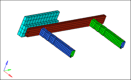
Bumper model
Step 1: Load the RADIOSS (Block) User Profile
| 1. | Launch HyperMesh Desktop. |
| 2. | From the Preferences menu, select the User Profiles or click the |
| 3. | Select RADIOSS (Block140) and click OK. |
Step 2: Load the bumper.hm file
| 1. | Click the Open Model icon |
| 2. | Click Open. |
The model loads into the graphics area.
Step 3: Define vehicle mass component to partially take into account the inertia properties and mass of the missing parts of the vehicle
| 1. | In the Model browser, right-click and select Create > Component. The Entity Editor (EE) will open. |
| 2. | For Name, enter Vehicle mass. |
| 3. | Set Card Image to None and click Yes to confirm. |
| 4. | Click Geometry > Create > Nodes > XYZ to open the Nodes panel. |
| 5. | In the X field, enter 700. |
| 6. | In the Y field, enter 0. |
| 7. | In the Z field, enter 170. |
| 8. | Click create to create the node. |
| 9. | Go to the 1D page, and click rigids. |
| 10. | Click the selector arrow nodes 2-n: and select sets. |
| 11. | For primary node, select the node created in the steps above. |
| 12. | Click sets and select the Constrain Vehicle set. |
| 13. | With all the DOF’s checked, click create to create the rigid body. |
|
| 14. | Click Card Edit |
| 15. | Click edit. |
| 16. | Fill the mass and inertia information in the card image, as shown in the table below: |
Mass |
JXX |
JXY |
JXZ |
JYY |
JYZ |
JZZ |
800 |
1.5E+07 |
-5.0E+03 |
-8.0E+06 |
5.0E+07 |
-900 |
6.0E+07 |
| 17. | Set ICOG as 4 and set Ispher as 0. |
| 18. | Click return to exit the panel. |
Step 4: Create a GRNOD/BOX/RECTA that contains all nodes except barrier nodes
| 1. | Click View > Browsers > HyperMesh > Solver to activate the Solver browser, if it is not active on your screen. |
| 2. | Right-click in the Solver browser and select Create > BOX > BOX/RECTA. The Entity Editor opens. |
| 3. | For Name, enter box velocity. |
| 4. | Optionally, select a Color. |
| 5. | Enter Corner1 and Corner2 X, Y, and Z coordinates, as shown below. |
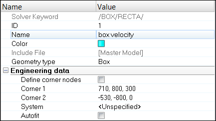
Step 5: Create initial velocity on bumper except barrier
| 1. | Click Tools > BCs Manager. |
| 2. | In the BCs Manager, enter Name as trans_vel. |
| 3. | Select the Select type as Initial Velocity under the Create header. |
| 4. | Set the entity selector to BOX under GRNOD. |
| 5. | Click on it and select box velocity. |
| 6. | Enter -10, 0, 0 for Vx, Vy and Vz fields, respectively. |
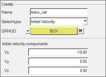
| 7. | After the above step, a set named InitialVelocity_grnodbox is created automatically or you can create this set before the above step and then refer to this set in the above step, instead of BOX. |
| 8. | Click the Create > Close. |
Step 6: Define master surface for contact
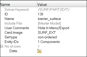
| 1. | Right-click in the Solver browser and select Create > SURF_EXT > PART. The Entity Editor opens. |
| 2. | For Name, enter barrier_surface. |
| 3. | For Entity IDs, click on Components. |
| 4. | In the Select Components dialog, select barrier and click OK. |
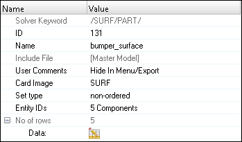
| 5. | Right-click in the Solver browser and select Create > SURF > PART. The Entity Editor opens. |
| 6. | For Name, enter bumper_surface. |
| 7. | For Entity IDs, click on Components. |
| 8. | In the Select Components dialog, select bumper, exterior crashbox left, exterior crashbox right, interior crashbox left, and interior crashbox right and click OK. |
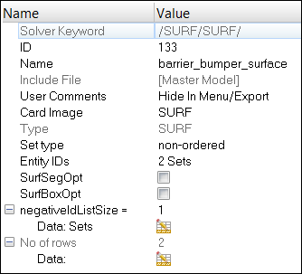
| 9. | Right-click in the Solver browser and select Create > SURF > SURF. The Entity Editor opens. |
| 10. | For Name, enter barrier_bumper_surface. |
| 11. | For Entity IDs, select Sets. |
| 12. | Click on Sets and select barrier_surface and bumper_surface and click OK. |
Step 7: Create self impact contact between parts of the bumper
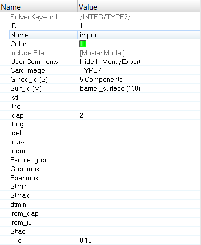
| 1. | Right-click in the Solver browser and select Create > INTER > TYPE7. The Entity Editor opens. |
| 2. | For Name, enter impact. |
| 3. | For Grnod_id (S) (slave entity), set the selector to Components. |
| 4. | Click Components, select bumper, interior crashbox (left and right) and exterior crashbox (left and right) and click OK. |
| 5. | For Surf_id (M) (master entity), set the selector to Set. |
| 6. | Click Set, select barrier_bumper_surface and click OK. |
| 7. | Set Igap to 2. |
| 8. | For the static coefficient Fric, enter 0.15. |
Step 8: Create a system that specifies the location and the cross section plane normal
| 1. | Click the numbering icon |
| 2. | Click the nodes selector and select by id. |
| 3. | For the IDs enter 6224, 6227, and 5993. |
| 4. | Check the display check box on. |
| 5. | Click on. |
|
| 6. | From the Analysis page, click systems. |
| 7. | Go to the create by node reference page. |
| 8. | Select Node ID 6224 for origin node. |
| 9. | Select Node ID 6227 for z- axis. |
| 10. | Select Node ID 5993 for yz plane. |
| 11. | Click create to create a system. |
| 12. | Click the Card Edit icon |
| 13. | Set the entity selector to systs. |
| 14. | Select the system and click edit. |
| 15. | Change the option from Skew to Frame. |
| 16. | Click return. |
Step 9: Create a set of elements that will contribute to the cross-sectional force results
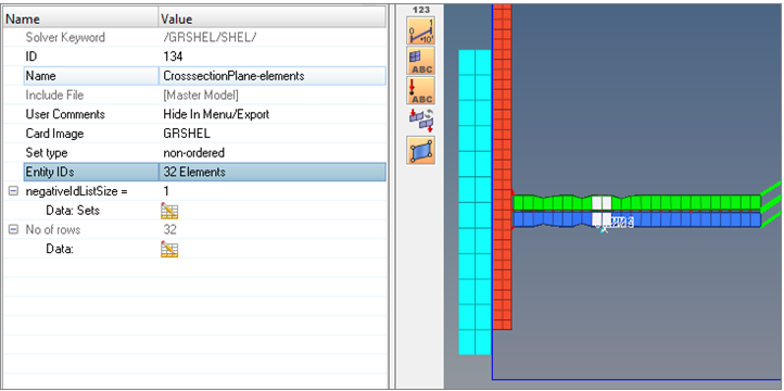
| 1. | Right-click in the Solver browser and select Create > GRSHEL > SHEL. The Entity Editor opens. |
| 2. | For Name, enter CrosssectionPlane-elements. |
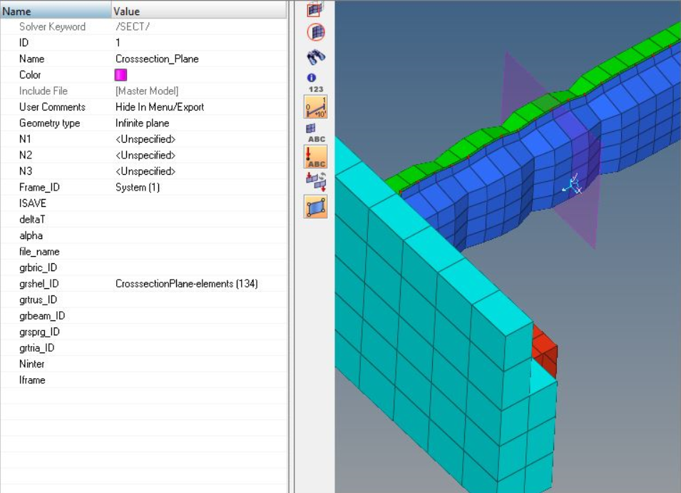
| 3. | For Entity IDs, toggle to Elements selector active, select two rows of element on either side of the system, as shown in figure below. |
Step 10: Define a section
| 1. | Right-click in the Solver browser and select Create > SECT > SECT. |
| 2. | For Name, enter Crosssection_Plane. |
| 3. | For Frame_ID, select the system defined in the previous step by clicking on the screen. |
| 4. | For grshel_ID, select the set CrosssectionPlane-elements which is defined in previous step, as shown below. |
Step 11: Select the section for time history output
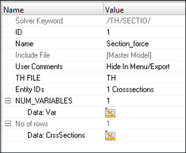
| 1. | Right-click in the Solver browser and select Create > TH > SECTIO. |
| 2. | For Name, enter Section_force. |
| 3. | For Entity IDs, toggle Crosssections and select Crosssection_Plane. |
| 4. | For NUM_VARIABLES, select 1 and for Data: Var, enter DEF. |
This selects the default output for RADIOSS.
Step 12: Create a BOX/RECTA and GRNOD/BOX containing the nodes making up the barrier and bumper’s left side
These nodes will be slave to the rigid wall.
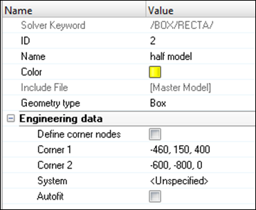
| 1. | Right-click in the Solver browser and select Create > BOX > BOXRECTA. |
| 2. | For Name, enter half model. |
| 3. | Optionally, select a Color. |
| 4. | Enter Corner1 and Corner2 X, Y and Z coordinates, as shown below: |
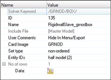
| 5. | Right-click in the Solver browser and select Create > GRNOD > BOX. |
| 6. | For Name, enter RigidwallSlave_grnodbox. |
| 7. | For Entity IDs, set the selector to Box and select the above created half model (BOX/RECTA). |
Step 13: Define a rigid wall
| 1. | Press the F8 key to enter the create nodes panel. |
| 2. | Select the XYZ ( |
| 3. | For x=, y= and z=, enter the values –600, -750 and 90, respectively. |
| 4. | Click create. |
| 5. | Right-click in the Solver browser and select Create > RWALL > PLANE. |
| 6. | For Name, enter wall. |
| 7. | Set Geometry type as Infinite Plane. |
| 8. | With the Base node selector active, select the node that was created in step 4. |
| 9. | Set Normal to 1,0,0. |
| 10. | For grnod_id1 (S), toggle Set and select RigidWallSlave_grnodbox (GRNOD/BOX). |
| 11. | For fric, specify 1.0 for the friction coefficient. |
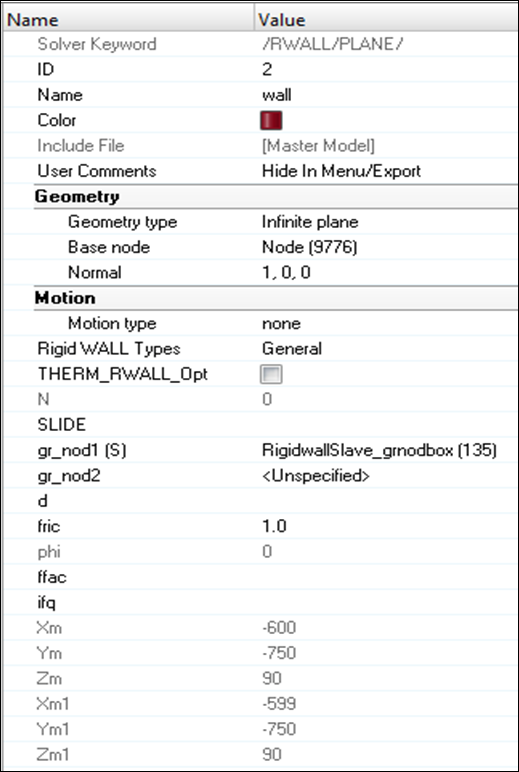
Step 14: Create output requests and control cards
| 1. | Launch the HyperMesh Solver browser from View > Browsers > HyperMesh > Solver. |
| 2. | Right-click in the Solver browser general area to create the cards, shown below with the given values for each parameter: |
Keyword Type |
Keyword |
Parameter |
Parameter Value |
|---|---|---|---|
CONTROL CARDS |
TITLE |
Status |
[Checked] |
CONTROL CARDS |
TITLE |
TITLE |
Bumper_Impact |
ENGINE KEYWORDS |
RUN |
Status |
[Checked] |
ENGINE KEYWORDS |
RUN |
Tstop |
20 |
ENGINE KEYWORDS |
PARITH |
Status |
[Checked] |
ENGINE KEYWORDS |
PARITH |
Keyword2 |
ON |
ENGINE KEYWORDS |
Status |
[Checked] |
|
ENGINE KEYWORDS |
N_Print |
-1000 |
|
ENGINE KEYWORDS |
TFILE |
Status |
[Checked] |
ENGINE KEYWORDS |
TFILE |
Time Frequency |
0.1 |
ENGINE KEYWORDS |
ANIM/ELEM |
Status |
[Checked] |
ENGINE KEYWORDS |
ANIM/ELEM |
EPSP |
[Checked] |
ENGINE KEYWORDS |
ANIM/ELEM |
VONM |
[Checked] |
ENGINE KEYWORDS |
ANIM/BRICK/TENS |
Status |
[Checked] |
ENGINE KEYWORDS |
ANIM/BRICK/TENS |
STRESS |
[Checked] |
ENGINE KEYWORDS |
ANIM/BRICK/TENS |
STRAIN |
[Checked] |
ENGINE KEYWORDS |
ANIM/SHELL/TENS/STRESS |
Status |
[Checked] |
ENGINE KEYWORDS |
ANIM/SHELL/TENS/STRESS |
MEMB |
[Checked] |
ENGINE KEYWORDS |
ANIM/SHELL/TENS/STRAIN |
Status |
[Checked] |
ENGINE KEYWORDS |
ANIM/SHELL/TENS/STRAIN |
MEMB |
[Checked] |
ENGINE KEYWORDS |
ANIM/VECT |
Status |
[Checked] |
ENGINE KEYWORDS |
ANIM/VECT |
DISP |
[Checked] |
ENGINE KEYWORDS |
ANIM/VECT |
VEL |
[Checked] |
ENGINE KEYWORDS |
ANIM/DT |
Status |
[Checked] |
ENGINE KEYWORDS |
ANIM/DT |
Tstart |
0 |
ENGINE KEYWORDS |
ANIM/DT |
Tfreq |
1 |
ENGINE KEYWORDS |
DT/NODA |
Status |
[Checked] |
ENGINE KEYWORDS |
DT/NODA |
CST 0 – Tmin |
3.6e-4 |
Step 15: Export the model
| 1. | Click File > Export or click the Export icon |
| 2. | For File:, click the folder icon |
| 3. | Enter the name bumper_impact and click Save. |
| 4. | Click the downward-pointing arrows next to Export options to expand the panel. |
| 5. | Toggle Merge starter and engine file to export the engine file with the model file (or export separately). |
| 6. | Click Export to export both model and engine file. |
Step 16: Run the solver using RADIOSS Manager
| 1. | Go to Start > Programs > Altair HyperWorks 14.0 > RADIOSS. |
| 2. | For Input file, browse to the exercise folder and select the file bumper_impact_0000.rad. |

Step 17 (Optional): View the results in HyperView
The exercise is complete. Save your work to a HyperMesh file.
See HyperMesh Tutorials for a complete list of tutorials.