|
»Click here to display Table of Contents«
|

/RWALL/LAGMUL |

|

|

|

|
|
/RWALL/LAGMUL |
|
|

|

|
|
»Click here to display Table of Contents«
|
/RWALL/LAGMUL |
|
|
|
|
|
/RWALL/LAGMUL |
|
|
|
|
Block Format Keyword
/RWALL/LAGMUL - Lagrange Multiplier Rigid Wall
Description
Defines infinite plane rigid walls using the Lagrange multiplier method. This keyword is not available for SPMD computation.
Format
(1) |
(2) |
(3) |
(4) |
(5) |
(6) |
(7) |
(8) |
(9) |
(10) |
/RWALL/LAGMUL/type/rwal_ID/unit_ID |
|||||||||
rwal_title |
|||||||||
node_ID |
Slide |
grnd_ID1 |
grnd_ID2 |
|
|
|
|
|
|
Dsearch |
|
|
|
|
|
|
|
|
|
XM |
YM |
ZM |
|
|
|
|
|||
Mass |
VX0 |
VY0 |
VZ0 |
|
|
||||
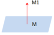
XM1 |
YM1 |
ZM1 |
|
|
|
|
|||
Blank Format |
|||||||||
|
|
|
|
See Also: