Shape variables are used in this example to vary both the thickness and the shape of a plate constructed from solid elements. Topography optimization allows discrete areas of the plate to change thickness and/or height, providing a greater range of possible solutions than with shape or size optimization alone.
A thin plate is built using two layers of solid elements. A uniform pressure is applied to the center portion of the plate (gray area) and the plate is simply supported at the corners.
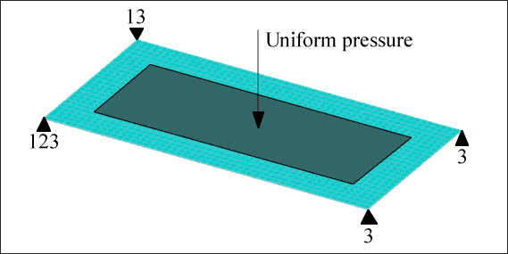
Loads and constraints for a plate to be optimized for both shape and size.
The design shape variables are generated externally to OptiStruct. Size variation is defined by creating a single design variable that controls the thickness of the plate. Shape variation is defined by creating a single design variable that controls the height of the plate relative to the constrained nodes.
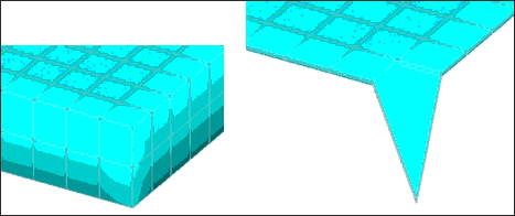
Models showing the size and shape variations at maximum thickness and height.
The two design variables are included in the finite element deck submitted to OptiStruct. Each variable has a single DESVAR card and a DVGRID for each node in the model affected by that variable. DTPG cards added to the deck reference the ID number of the DESVAR cards as follows:
DESVAR
|
1
|
DV001
|
0.25
|
0.0
|
0.25
|
|
|
|
DESVAR
|
2
|
DV002
|
0.75
|
0.0
|
0.75
|
|
|
|
DTPG
|
3
|
DVGRID
|
1
|
|
|
|
|
|
|
3.0
|
60.0
|
YES
|
|
|
|
|
|
DTPG
|
4
|
DVGRID
|
2
|
|
|
|
|
|
|
3.0
|
60.0
|
NO
|
|
|
|
|
|
DVGRID*
|
1
|
4
|
0
|
1.0
|
*
|
0.000000000E+00
|
9.9999999748E-07
|
5.0000000000E+00
|
|
DVGRID*
|
1
|
5
|
0
|
1.0
|
*
|
0.000000000E+00
|
9.9999999748E-07
|
5.0000000000E+00
|
|
…
|
|
|
|
|
Entries in fields 15 through 18 are not required because the draw vectors are already defined for each node on the DVGRID cards. A buffer zone is requested for the shape variable that ensures a smooth transition between the constraints and the rest of the structure. Lengthwise symmetry is enforced (the left side of the plate mirrors the right side).
The compliance of the part was minimized with the mass of the part constrained to be below a given value.
The solution is shown in the figures below.
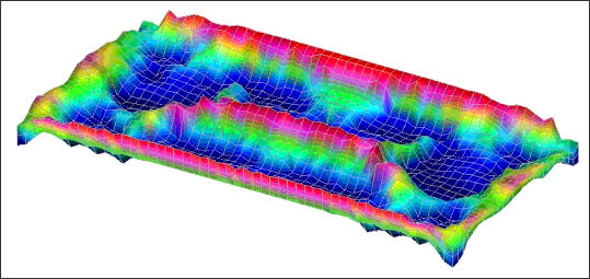
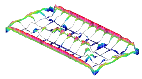
OptiStruct solution for shape and size optimization of plate in bending, top view.
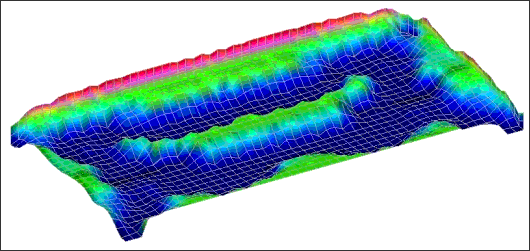
OptiStruct solution for shape and size optimization of plate in bending, bottom view.
OptiStruct creates a thick rib around the perimeter of the plate, providing a solid foundation for the attachment of the remaining design features. The highest degree of bending occurs at the center of the part, with the largest bending component running in the longitudinal direction. The plate is stiffened in this direction when OptiStruct creates a central rib and a W-shaped reinforcement pattern by raising the thick areas of the plate and lowering the thin areas of the plate. This shape employs the entire structure, not just the parts with ribs.
Cross-sections of the optimized shape and size of the plate in bending.
For the input file sample, see <install_directory>/demos/hwsolvers/optistruct/sizeandshape.fem.
See Also:
Example Problems for Topography Optimization


