Surface Optimization of a Control Arm |

|

|

|

|
|
Surface Optimization of a Control Arm |

|

|

|

|
Topography optimization has applications beyond creating beads in shell surfaces. Since the basic topography approach can be applied to any model containing large fields of shape variables, it lends itself to solid model applications as well. In the following example, global shape optimization of a solid part is performed by generating shape variables using the DTPG card.
The solid control arm model is based on the topology optimization results as shown in the figure below. After a basic material layout is generated using topology optimization, the solution can be refined to meet design specifications using shape optimization. However, it can be a very time consuming procedure if done by hand. By automating the procedure of generating shape variables over the entire surface of a solid part, OptiStruct allows users to quickly set up the shape optimization model.
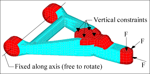
Loads and constraints for solid control arm.
To use topography optimization to optimize the surface of a solid model, the areas to be optimized must first be covered with shell elements (see gray elements in figure below).
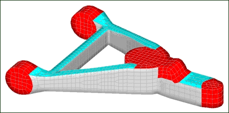
Solid control arm model partially covered in shell elements (gray areas).
The side surfaces of the structural members are optimized in this example.
Shells are attached to the sides of the members. Define the normal vectors of those elements to point inward. Set the value of the draw height on the DTPG card so that the solid elements do not get turned inside out during shape optimization. If this occurs, OptiStruct gives an error and terminates the optimization. The lower bound on the DTPG card was set to –1.0 and the upper bound was set to 1.0, which allows the control arm to become larger or smaller.
The objective was set as minimizing the weighted sum of the compliance of the load cases while holding the mass of the part constant.
OptiStruct reduces the thickness of the rear crossbar and shapes the struts on either side to resemble C-sections. The front member is tapered to be smaller the closer it is to the area of the applied loads.
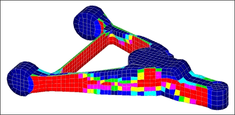
OptiStruct solution for surface optimized control arm, areas to be thinned are red.
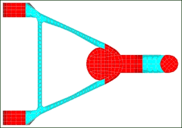
OptiStruct undeformed model for surface optimized control arm, top view.
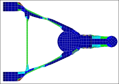
OptiStruct solution for surface optimized control arm, top view.
For the input file sample, see <install_directory>/demos/hwsolvers/optistruct/solidarm.fem.
See Also: