Model Description
Model location: <altair>\utility\mbd\nlfe\validationmanual\model2.mdl
This model consists of a straight beam fixed to the ground at one end and subject to a vertical load at the other end. The beam is also subjected to gravity as shown in Figure 1 below.
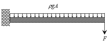
Figure 1: A beam of fixed at one end and subject to self-weight and a load at the other end
Small deformations for such a beam can be obtained using the Euler-Bernoulli beam theory as:

|
Vertical deformation of the end point of the beam mm.
|

|
Applied end force.
|

|
Beam length.
|

|
Young’s modulus.
|

|
Moment of inertia about the axis normal to the page.
|

|
Beam density.
|

|
Acceleration due to gravity.
|

|
Beam cross section area.
|
Multi-Body Model
The cantilever beam is modeled using 20 NLFE beam elements in MotionSolve. The cantilever beam is fixed to the ground by a fixed joint.
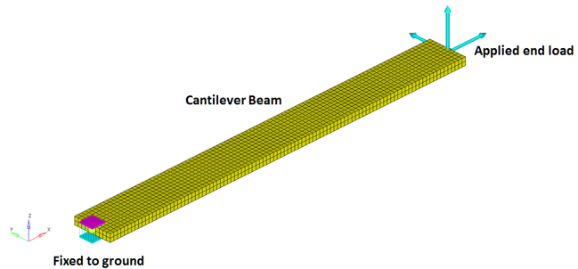
Figure 2: The cantilever beam modeled in MotionView
An end force is applied at the end of the cantilever beam using a ForceOnly Force_Vector_OneBody element. A force of -2000 N is applied gradually, via a STEP function as:
This model is simulated with an end time of 5 seconds, for a dynamic analysis. Under the end force, the beam is expected to deflect in the vertical direction by an amount predicted by the theoretical model.
The following material properties are used for the NFLE beam:

|
5000 mm
|

|
50000 mm2
|

|
41.66 x 106 mm4
|

|
7.86 x 10⁻⁶ kg/mm3
|

|
2.1 x 10⁵ N/mm2
|
Based on these material properties and the applied load, the expected deflection is:
No gravity:
= -9.525 mm
With gravity:

= -43.9531 mm
The Z displacement of the last grid point will be used to determine the end point deflection. This is available as a standard output in the MRF output file.
Numerical Results
The multi-body model described in the previous section is run for an end time of 5.0 seconds. The Z displacement of the last grid point is plotted below. The blue line depicts the displacement when gravity is included in the model and the red line depicts the displacement when gravity is turned off.
The plots above show that the displacement of the end node of the beam changed during the simulation due to the bending deformation:
DZ
|
g=9.81m/s2
|
g=0
|
-43.9305 mm
|
-9.522 mm
|
Conclusion
The NLFE model with 20 BEAM elements shows close agreement to the theoretical results for this case.
|
Euler-Bernoulli
|
Numerical
|
% error
|
DZ (gravity on)
|
-43.95 mm
|
-43.93 mm
|
0.05 %
|
DZ (gravity off)
|
-9.53 mm
|
-9.52 mm
|
0.11 %
|
The results presented use the default solver settings present in MotionView.


