Model Description
Model location: <altair>\utility\mbd\nlfe\validationmanual\model3.mdl
This model consists of a straight beam fixed to the ground at one end and subject to a moment load at the other end as shown in Figure 1 below. To curl the beam into a circle, the following load is applied:

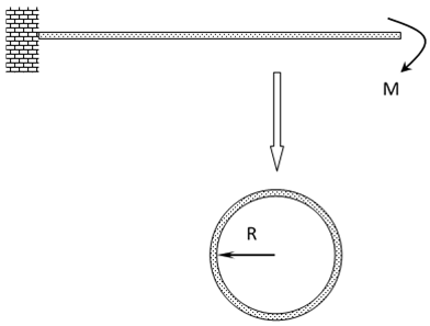
Figure 1: A cantilever beam fixed at one end and subject to a load at the other end curls up into a circle for large deformation
Here,

|
Applied moment at the end point.
|

|
Young’s modulus.
|

|
Moment of inertia about the axis normal to the page.
|

|
Radius of the deformed circular shape.
|

|
Beam length.
|
Multi-Body Model
The cantilever beam is modeled using 250 NLFE BEAM elements in MotionSolve. The left end of cantilever beam is fixed to the ground by a fixed joint. The right end has a planar joint with ground (this is to minimize numerical instability and aid in the simulation. This does not affect the physics). Gravity is turned off for this model. The moment is applied at the right end of the beam.
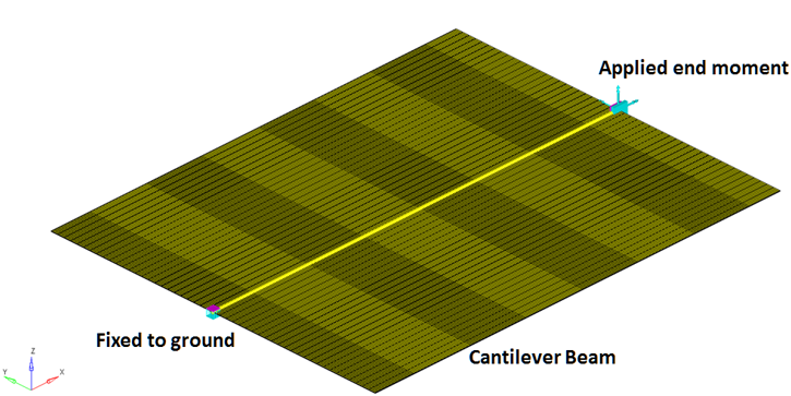
Figure 2: The cantilever beam modeled in MotionView
An end moment is applied at the end of the cantilever beam using a TorqueOnly Force_Vector_OneBody element. The moment is applied using the following equation:
The following material properties are used for the NFLE beam:

|
5000 mm
|

|
31840 mm2
|

|
1.68 x 105 mm4
|

|
7.8 x 10⁻⁶ kg/mm3
|

|
2.1 x 10⁵ N/mm2
|
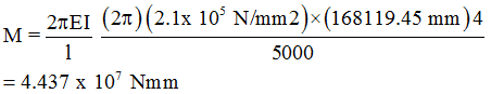
For the above values, the applied moment load is:
This model is simulated with an end time of 40 seconds, for a dynamic analysis. The moment load is applied using a step function that ramps up in 35 seconds. Under the end moment, the beam is expected to deform and curl up into a perfect circle with a radius 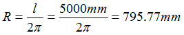 .
.
The actual radius of the deformed beam can be determined by calculating the Z displacement of the node at the midpoint of the beam and dividing the value by 2.
Numerical Results
Figure 3 below depicts the deformation of the cantilever beam under the end moment load. Tracing is turned on so the deformation of the beam can be visualized. The yellow component represents the un-deformed shape and the component with contours represents the final deformed shape at the end of the simulation. The trace of last element of the beam (grey) can also be visualized as it deforms during the simulation. As can be seen, there is a large rotation of this element from the un-deformed to the final deformed state.
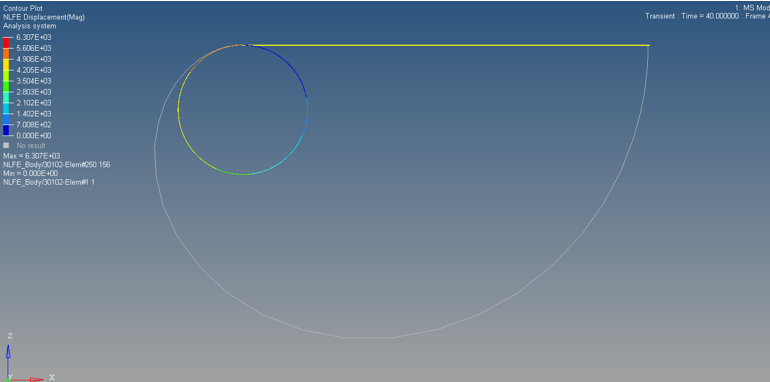
Figure 3: Magnitude of displacement for the endpoint node
To determine the radius of the deformed shape, you can plot the Z displacements of GRID/301127 (the mid-point of the beam) from the MRF file and divide the value by 2.
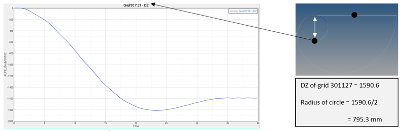
Figure 4: Z displacement for GRID/301127
Conclusion
The NLFE model with 250 BEAM elements shows close agreement to the theoretical results for this case.
|
Theoretical
|
Numerical
|
% error
|
Radius
|
795.77 mm
|
795.3 mm
|
0.06
|
The results presented use the default solver settings present in MotionView.


