Model Description
Model location: <altair>\utility\mbd\nlfe\validationmanual\model4.mdl
This model consists of a truss structure composed of seven straight beams of a 0.01m*0.01m cross section as shown in Figure 1 below.
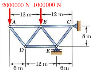
Figure 1: A truss structure attached to the ground via pin (revolute) joint and Inplane joint.
A load of 2000000N and 1000000N is applied in the downward direction at point A and B respectively.
Multi-Body Model
Each beam member is modeled using a single NLFE beam element in MotionSolve. Gravity is turned off for this model. The truss is attached to the ground via revolute joint at point C and via Inplane joint at point E. The joints between the beams are all revolute joints.
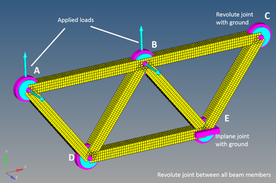
Figure 2: The truss structure modeled in MotionView
The load of 2000000N and 1000000N is applied in the negative Y direction at points A and B. The following material properties are used for the NFLE beam:

|
1 m2
|

|
7860 kg/m3
|

|
2.1 x 10¹¹ N/m2
|

|
0.3 (Poisson ratio)
|
For the above values, the theoretical axial stress (force/area) in each of the beam members is:
Beam
|
Theoretical Axial Stress N/m2
|
AB
|
1500 x 103
|
BC
|
5250 x 103
|
AD
|
2500 x 103
|
DB
|
2500 x 103
|
BE
|
3750 x 103
|
EC
|
8750 x 103
|
DE
|
3000 x 103
|
This model is simulated with an end time of 5 seconds, for a quasi-static analysis.
Numerical Results
Figure 3 below depicts the final state of the truss structure under the load. The contours depict the axial stresses in each beam member (ignoring the local values at the joint locations).
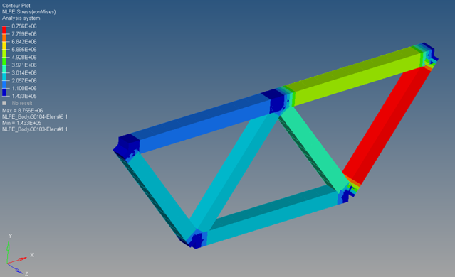
Figure 3: Axial stresses in the beam members of the truss
The axial stresses are written to the H3D file and their contours can be visualized in HyperView as shown in Figure 3. The numerical values of these axial stresses are summarized below.
Beam
|
Numerical Axial Stress N/m2
|
AB
|
1505 x 103
|
BC
|
5255 x 103
|
AD
|
2501 x 103
|
DB
|
2501 x 103
|
BE
|
3749 x 103
|
EC
|
8752 x 103
|
DE
|
3001 x 103
|
Conclusion
The NLFE model with 7 BEAM12 elements show close agreement to the theoretical results for this case.
Beam
|
Theoretical Axial Stress N/m2
|
Numerical Axial Stress N/m2
|
% error
|
AB
|
1500 x 103
|
1505 x 103
|
0.33
|
BC
|
5250 x 103
|
5255 x 103
|
0.1
|
AD
|
2500 x 103
|
2501 x 103
|
0.04
|
DB
|
2500 x 103
|
2501 x 103
|
0.04
|
BE
|
3750 x 103
|
3749 x 103
|
0.03
|
EC
|
8750 x 103
|
8752 x 103
|
0.02
|
DE
|
3000 x 103
|
3001 x 103
|
0.03
|
The results presented use the default solver settings present in MotionView.


