Model Description
Model location: <altair>\utility\mbd\nlfe\validationmanual\model5.mdl
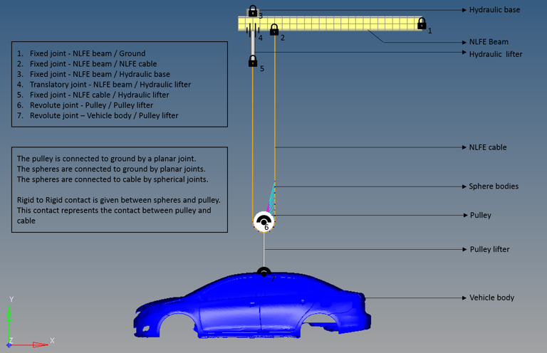
This model consists of a crane with a beam structure. A hydraulic lifter is placed at the tip of the beam which lifts a car frame with the aid of a cable pulley system with a mechanical advantage equal to 2.
It is to be validated that the load transferred to the hydraulic lifter is only half of the actual load that is being lifted, due to the effect of cable pulley system.
Multi-Body Model
The beam is modeled with a single NLFE beam of I-section. The rope is modeled using 68 NLFE cable elements. The pulley, hydraulic base, hydraulic lifter, pulley lifter and so on are modeled as rigid cylinders. There are a number of sphere bodies used to establish contact between the cable and pulley. Gravity is kept ON for this model.
The various joints between the bodies in the crane are as shown in the figure below.

Figure 1: The crane modeled in MotionView
The suspended load and the load transferred to the hydraulic lifter can be calculated as follows:
Suspended load = vehicle weight + pulley weight + pulley lifter weight
= (300 * 9.81) + (13.3002 * 9.81) + (0.5777 * 9.81)
= 3079 N
Mechanical advantage of rope pulley system = 2
Load transferred to the hydraulic lifter = suspended load / mechanical advantage
= 3079 / 2
= 1539
The motion to the hydraulic lifter is given as a step function, where the lifting speed is ramped from 0 to 15 mm/s in four seconds using a STEP function as shown below:
`Step (time, 0, 0, 4, -15) `
This model is simulated with an end time of 10 seconds, for a transient analysis.
Numerical Results
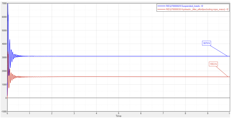
Figure 2 below depicts the actual suspended load (blue line) and the load transferred to the hydraulic lifter (red line).

Figure 2: Plots showing suspended load and the load transferred to the Hydraulic lifter.
Conclusion
The NLFE model shows close agreement to the theoretical results for this case.
|
Theoretical
|
Numerical
|
% error
|
Suspended load
|
3079 N
|
3079 N
|
0 %
|
Load transferred to hydraulic lifter
|
1539 N
|
1553 N
|
0.9 %
|


