Level Set Method (Beta) |

|

|

|

|
|
Level Set Method (Beta) |

|

|

|

|
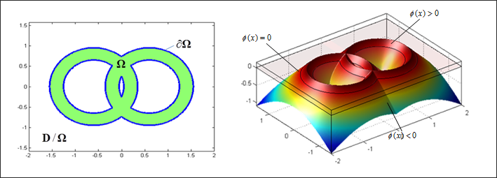
A new topology optimization algorithm based on the level set method was implemented in OptiStruct 12.0. In the level set method, the boundary of the design is implicitly represented as the isosurface (the zero level set) of a function ![]() defined on the finite element mesh, as shown in the figure below. In the level set model, the domain is defined based on the value of the level set function:
defined on the finite element mesh, as shown in the figure below. In the level set model, the domain is defined based on the value of the level set function:

Where, D specifies the design domain; ![]() represents the material region,
represents the material region, ![]() stands for the boundary and
stands for the boundary and ![]() represents the region with no material. The dynamic motion of the boundary is governed by the so-called, level set equation:
represents the region with no material. The dynamic motion of the boundary is governed by the so-called, level set equation:

Where, ![]() is the normal velocity and
is the normal velocity and ![]() is the norm of the gradient of the level set function. The basic idea of the level set equation is to map the boundary evolution into an evolution of the level set function
is the norm of the gradient of the level set function. The basic idea of the level set equation is to map the boundary evolution into an evolution of the level set function ![]() .
.

A 2D Design and its corresponding Level Set representation
Level-set based topology optimization can be considered as advanced shape optimization. It works like conventional shape optimization, where the design is changed by moving the boundary, while at the same time topological changes, such as boundary emerging and splitting can be handled naturally.
The following procedure can be considered as a guide to setup Level-set Optimization:
| 1. | Level-set Optimization is OFF by default for topology optimization in OptiStruct. |
| 2. | It can be switched ON by adding the LEVELSET continuation line on the DTPL entry. |
(1) |
(2) |
(3) |
(4) |
(5) |
(6) |
(7) |
(8) |
(9) |
(10) |
DTPL |
1 |
PSHELL |
7 |
8 |
17 |
|
|
|
|
|
LEVELSET |
ALIGN |
|
|
|
|
|
|
|
| 3. | An example input DTPL entry is shown above. This will activate the Level-set method for topology optimization. The fields on the LEVELSET continuation line can be used to control the implementation. Refer to the DTPL Bulk Data Entry for further information. |
See Also: