In this tutorial, you will learn how to use the four sub-tabs that comprise the CAD tab by:
| • | Comparing CAD geometry (CAD IO) |
| • | Comparing CAD geometry across different HyperMesh versions (Compare Versions) |
| • | Comparing the original CAD geometry and an FE mesh after meshing in HyperMesh (CAD > Mesh) |
| • | Comparing Meshed FE geometry across different HM versions (FE-FE) |
Step 1: Compare CAD geometry (CAD IO tab)
| 1. | From the Start menu, select All Programs > Altair HyperWorks 2017 > Tools > HyperWorks Verification and Validation Harness. |
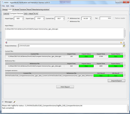
| 2. | Select the CAD tab, followed by the CAD IO tab. |
| 3. | From the Import file type: drop-down menu, select the Import file type IGES. |
| 4. | From the Export file type: drop-down menu, select STEP |
| 5. | For HW Version, select 2017. |
| 6. | Leave Tolerance as the default (.01). |
| 7. | Under the Input File field, click the file folder icon,  , to search for and load additional input files. , to search for and load additional input files. |
| 8. | Click the add file icon,  , to display the file browser and load the raw_iges_data.iges file from the following location: ..\tutorials\hvvh\CAD\CADIO. , to display the file browser and load the raw_iges_data.iges file from the following location: ..\tutorials\hvvh\CAD\CADIO. |
| 9. | For the Output directory field, use the open file icon,  , to select an output directory. , to select an output directory. |
| 11. | A report is generated based on the model re-import and comparison with the original CAD geometry, a CAD-CAD comparison. Model file import and export times, as well as import and export status are displayed. |
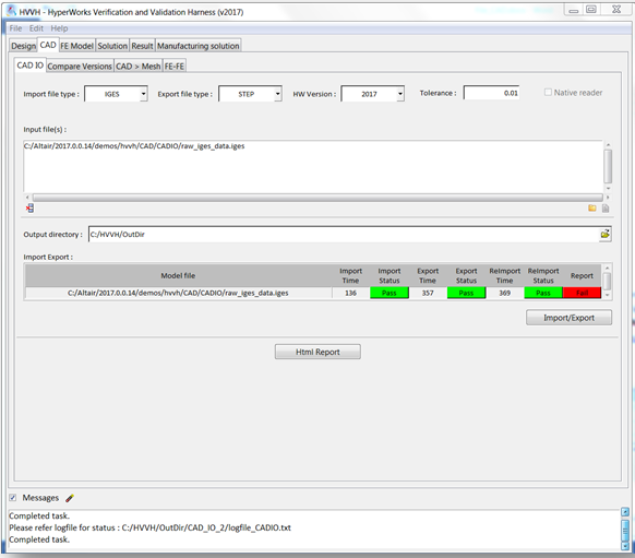
In the Messages window, the run details are displayed along with the log file location.
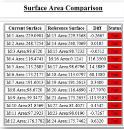
If a difference is greater than the tolerance, it is indicated as Fail, otherwise shown to Pass.
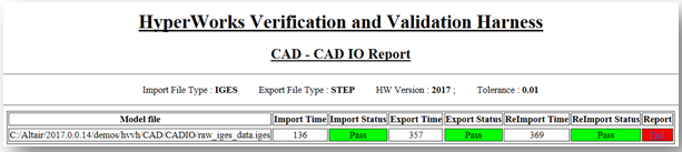
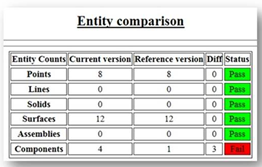
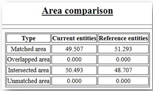
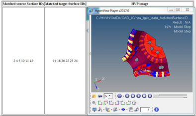
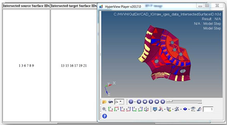
| 12. | Click HTML Report to generate a detailed CAD IO report, similar to this: |
Step 2: Compare CAD geometry across different HyperMesh versions (Compare Versions tab).
| 1. | Select the Compare Versions tab. |
| 2. | From the Import file type: drop-down menu, select the Import file type IGES. |
| 3. | From the Export file type: drop-down menu, select STEP. |
| 4. | For Current Version, select 2017. |
| 5. | For Reference Version, select 14.0.0.130. |
| 6. | Leave Tolerance as the default (.01). |
| 7. | Under the Input File field, click the file folder icon, , to search for and load additional input files. |
| 8. | Click the add file icon, , to display the file browser and load the raw_iges_data.iges file from the following location: ..\tutorials\hvvh\CAD\CompareVersions. |
| 9. | For the Output directory field, use the open file icon, , to select an output directory. |
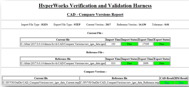
| 11. | A report is generated based on the comparison of exported CAD geometry in the current and reference versions and CAD-CAD comparison. Model file import and export times, as well as import and export status are displayed for both the current and reference versions. |
In the Messages window, the run details are displayed along with the log file location.
If a difference is greater than the tolerance, it is indicated as Fail, otherwise shown to Pass.
| 12. | Click HTML Report to generate a detailed report of the CAD version comparison operations, similar to this: |
Step 3: Compare original CAD geometry and an FE mesh after meshing in HyperMesh (CAD > Mesh tab).
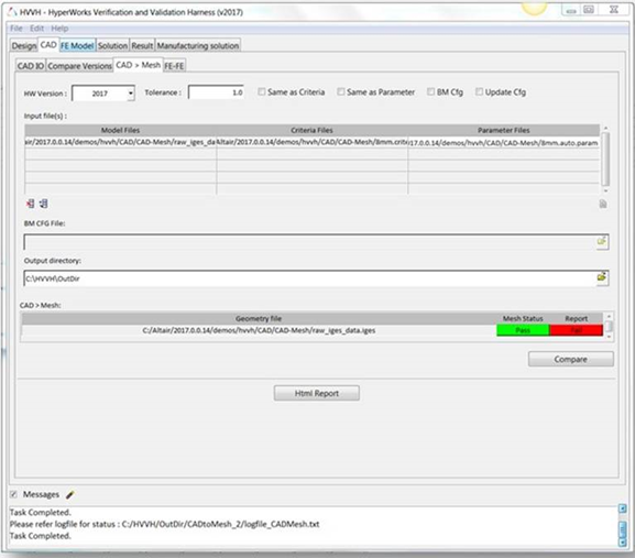
| 1. | Select the CAD > Mesh tab. |
| 2. | From the Import file type: drop-down menu, select the Import file type IGES. |
| 3. | From the Export file type: drop-down menu, select STEP. |
| 4. | For Current Version, select 2017. |
| 5. | Leave Tolerance as the default (.01). |
| 6. | Leave the following options blank: Same as Criteria, Same as Parameter, BM Cfg, and Update Cfg. |
| 7. | To select the Model File under the Input File heading, click the add file icon, , to display the file browser and load the raw_iges_data.iges file from the following location: ..\tutorials\hvvh\CAD\CAD-Mesh. |
| 8. | To select the Criteria File under the Input File heading, click the add file icon, , to display the file browser and load the 8mm.criteria file from the following location: ..\tutorials\hvvh\CAD\CAD-Mesh. |
| 9. | To select the Parameter File under the Input File heading, click the add file icon, , to display the file browser and load the 8mm.auto.param file from the following location: ..\tutorials\hvvh\CAD\CAD-Mesh. |
| 10. | For the Output directory field, use the open file icon, , to select an output directory. |
| 12. | In the background, a CAD model is imported in HyperMesh and it is meshed based on the selected criteria and parameter files. |
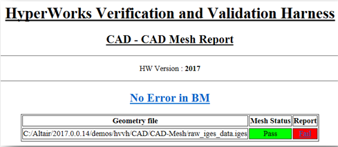
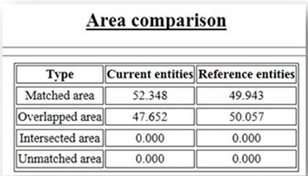
| 13. | A report is generated based on the comparison of CAD geometry and the meshed FE model CAD-Mesh comparison. The mesh status is displayed and any issues are displayed as Fail. |
In the Messages window, the run details are displayed along with the log file location.
| 14. | Click HTML Report to generate a detailed report of the CAD > Mesh comparisons, similar to this: |
Step 4: Compare meshed FE geometry across different versions of HyperMesh (FE > FE tab).
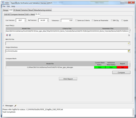
| 1. | Select the FE > FE tab. |
| 2. | From the Import file type: drop-down menu, select the Import file type IGES. |
| 3. | From the Export file type: drop-down menu, select STEP. |
| 4. | For Current Version, select 2017. |
| 5. | For Reference Version, select 14.0.0.130. |
| 6. | Leave Tolerance as the default (.01). |
| 7. | Leave the following options blank: Same as Criteria, Same as Parameter, BM Cfg, and Update Cfg. |
| 8. | To select the Model File under the Input File heading, click the add file icon, , to display the file browser and load the raw_iges_data.iges file from the following location: ..\tutorials\hvvh\CAD\FE-FE. |
| 9. | To select the Criteria File under the Input File heading, click the add file icon, , to display the file browser and load the 8mm.criteria file from the following location: ..\tutorials\hvvh\CAD\FE-FE. |
| 10. | To select the Parameter File under the Input File heading, click the add file icon, , to display the file browser and load the 8mm.auto.param file from the following location: ..\tutorials\hvvh\CAD\FE-FE. |
| 11. | For the Output directory field, use the open file icon, , to select an output directory. |
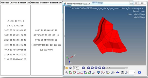
| 13. | In the background, a CAD model is imported in HyperMesh and it is meshed based on the selected criteria and parameter files. |
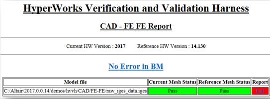
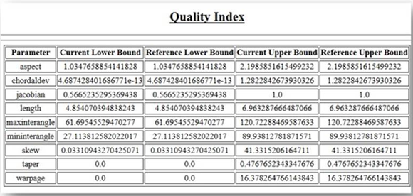
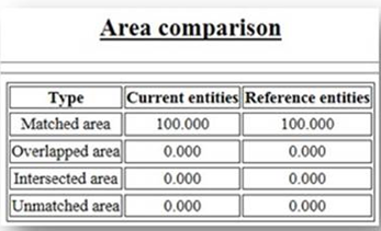
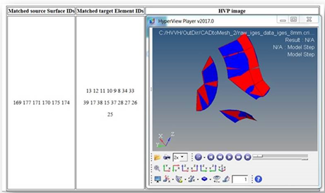
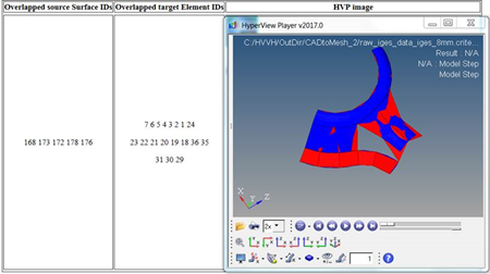
| 14. | A report is generated based on the comparison of the meshed FE models (FE-FE). The mesh status is displayed and any issues are displayed as Fail. |
In the Messages window, the run details are displayed along with the log file location.
| 15. | Click HTML Report to generate a detailed report of the FE-FE comparison, similar to this: |