|
»Click here to display Table of Contents«
|

Mount Limits |

|

|

|

|
|
Mount Limits |
|
|

|

|
|
»Click here to display Table of Contents«
|
Mount Limits |
|
|
|
|
|
Mount Limits |
|
|
|
|
The Altair Bushing Model includes a Mount Limits feature, which lets you model the material contact that occurs between the bodies that a bushing connects. The bodies are flexible and may deflect under the load being transmitted. Given enough bushing deflection, the bodies may contact one another for negative and positive deflections in each direction. See also: Mount Stiffness.
When bushings deflect, a large amount of contact can occur between the bodies they connect limiting the deflection. However, these limits are dependent on the geometry of the bodies and are not an intrinsic bushing property. Therefore mount limits are specified in a separate Mount Limits Property File (*.gbi). In this file you can:
| • | Activate mount limits for a bushing. |
| • | Define gap, stiffness and damping properties that are appropriate for the bodies that the bushing connects. |
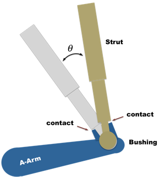
When the bushing deflection closes the gap between the bodies in a specific direction, the mount limit in the corresponding direction exerts a force or torque to limit the deflection. The following image shows how such a contact can occur at the connection between the A-Arm and the Strut in a suspension.
The mount limit force or torque adds to the bushing force or torque and acts to increase the normal force or torque input to the bushing friction and the local deflection of the bodies.
Mount Limits depend on the geometry of the bodies that mount the bushing, and not the bushing itself. Therefore, the displacement and velocity used for computing the mount limit forces and moments, unlike the bushing, is not scaled, offset or coupled.
You can define positive and negative mount limits for any set of bushing directions: {FX, FY, FZ, TX, TY, and TZ}.
| • | A positive mount limit acts to limit positive displacement in a given direction by producing a negative force or torque. |
| • | A negative mount limit acts to limit bushing negative displacement and produces a positive force or torque. |
| • | All the input parameters like stiffness, gap, and exponent for either positive or negative mount limits are always entered as positive values. |
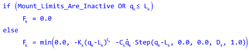
Let:
Then the force or torque in the kth direction for a positive mount limit is defined as:
|
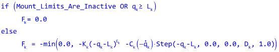
For a negative mount limit, the limit force is computed in the same manner as a positive mount limit, however the input displacement and velocity are negated as is the output force. Again all the input parameters are positive. The force/torque computation for a negative mount limit is:
|