Process Data |

|

|

|

|
|
Process Data |

|

|

|

|
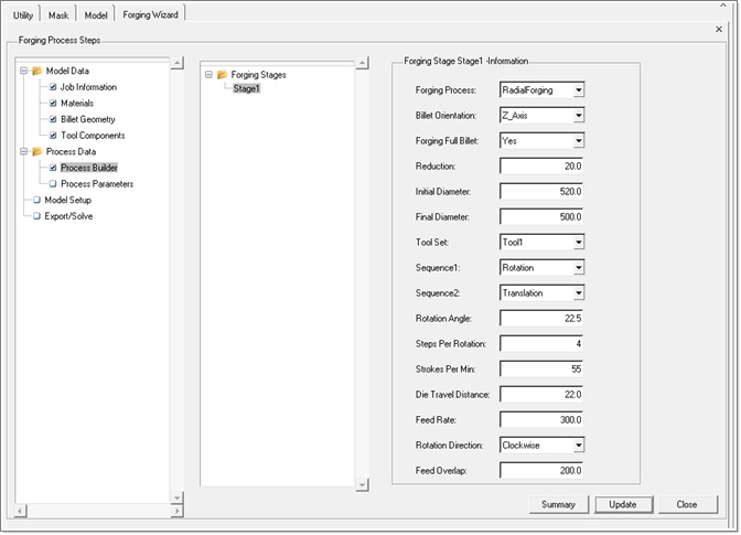
This step allows you to specify the details of the forging process. At present, press forging and radial forging are supported.
In the Process Builder, you will enter the information about each forging /reduction stage. For each stage, the key parameters such as forging process, reduction, the tool set (must have been already defined in the previous step) used for this stage are specified. In addition, you should also specify the feed sequence in which the work piece is hit by the forging punch. All parameters specific to the forging stage are explained below.

Name |
Description |
Forging Process |
At present, only Radial Forging and Press Forging are supported. |
Billet Orientation |
It is the direction in which the work piece is advanced during the forging process. The default is Z-Axis (positive) direction. |
Forging Full Billet |
It tells whether the forging is performed over the entire length of the billet. The allowed options are Yes/No. At present, only option Yes is supported, that means only full length of the billet is forged. The other option is included to allow forging only a portion of the billet in future. |
Reduction |
Amount of reduction achieved in the characteristic dimension of the billet (in case of a circular billet, it is reduction of diameter) |
Initial Diameter |
For the first stage it is the same as the original billet diameter. And for the subsequent stages, the initial diameter for the current stage is equal to the billet diameter at the end of the previous forging stage. |
Final Diameter |
For the current stage Final diameter is the diameter of the billet at the end of this forging stage. Final Diameter = Initial Diameter – Reduction |
Tool Set |
Tool set should be selected according to the current forging process. If the forging process is Radial Forging, you should select the tool set for the radial forging. And moreover this tool set must have been defined during Tool Components step under Model Data. |
Sequence 1 |
Sequence1 and Sequence2 describe how the billet moves during the forging process. For example, if Sequence1 is specified as Rotation and Sequence2 as Translation , first work piece is rotated with a specified Rotation Angle between two consecutive punch blows until reduction is applied over the entire circumference of the workpiece. Then workpiece is advanced in BilletOrientation direction with a specified feed rate. |
Sequence 2 |
|
Rotation Angle |
Indicates the angle at which workpiece rotates between two consecutive punch blows |
Steps per Rotation |
Number of rotation steps the workpiece should undergo in order to ensure that it is hit uniformly along the circumference. |
Strokes per Min |
Number of punch strokes per minute. |
Die Travel Distance |
The distance a die (punch) travels freely before hitting the workpiece. |
Feed Rate |
The distance the workpiece advances in the translation direction in each translation step. |
Rotation Direction |
It specifies the rotation direction of the workpiece during the forging process. Valid options are Clockwise, Counterclockwise and No Rotation. |
Feed Overlap |
It determines the position of the billet at the start of forging process for the current stage. The billet is positioned such that the end of the billet is at a distance equal to Feed Overlap inside the punch in Billet Orientation Direction at start of each forging stage. Feed Overlap value should be carefully selected to ensure the billet is uniformly hit over the entire circumference before it elongates beyond the punch. |
Each Forging Stage information is exported as a separate data packet in a *.grf file as shown below.
ForgingStage Stage1 { |
|
Process |
= "RadialForging" |
BilletOrientation |
= "Z_Axis" |
ToolSetName |
= "Tool1" |
ForgingFullBillet |
= "Yes" |
Reduction |
= 20.0 |
FirstFeed |
= "Rotation" |
SecondFeed |
= "Translation" |
RotationAngle |
= 22.5 |
RotationDirection |
= "Clockwise" |
NumRotationSteps |
= 4 |
PunchStrokesPerMin |
= 55 |
PunchTravelDistance |
= 22.0 |
FeedRate |
= 300.0 |
FeedOverlap |
= 200.0 |
} |
|
Total simulation can comprise several forging stages. The number of forging stages and sequence in which the forging stages are performed are exported as a ForgingSequence data packet.
ForgingSequence ForgeSequence { NumForgingStages = 4 Sequence = "Stage1" “Stage2” “Stage3” “Stage4” } |
Process parameters are arranged in four different groups, each under a separate tab.
Note: The process parameters under these tabs are exported into *.frg file.
Process parameters, for which you will specify values different from corresponding default values will surely be written in the *.frg file. Otherwise only critical process parameters are written in *.frg file. For those parameters that are not written in *.frg file, default values are applied by the solver.
The Session tab contains the information about the nonlinear tolerance and maximum number of nonlinear iterations.
|
|
This tab contains the advanced parameters such as relaxation factors used in temperature, velocity, and pressure calculation.
On this tab, you can set advanced numerical parameters used by the solver.
|
|