The following steps outline how to build a MacPherson strut suspension using the Assembly Wizard. Other suspensions use similar dialogs; however the build process varies based on the suspension type.
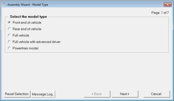
| 1. | Select Front end of vehicle to build a front suspension and steering system. Select Next to move to the next dialog. |
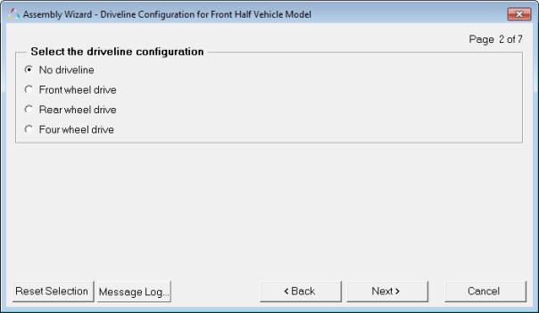
| 2. | Select the type of driveline you want to include or No driveline. |
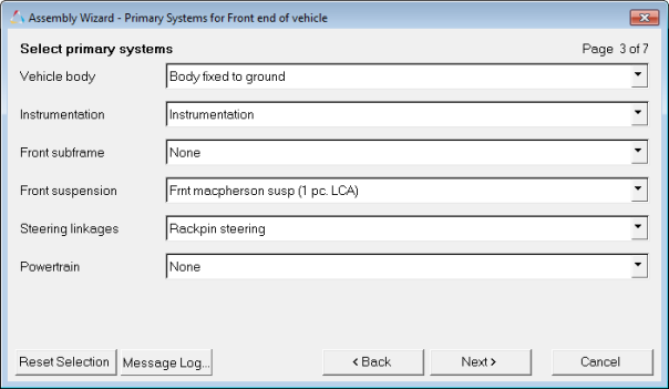
| 3. | For the Vehicle body, select Body fixed to ground or None. This option includes a vehicle body part in the model. |
| - | Select a Front subframe or None if your model should include an isolated front subframe. |
| - | Select one of the five available front suspensions. |
| - | Select one of the three types of steering systems. |
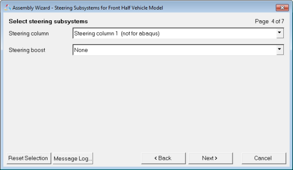
| 4. | Select Steering column 1 to include a steering column with two universal joints. |
| - | Select the boost model to include steering system hydraulic boost effects. |
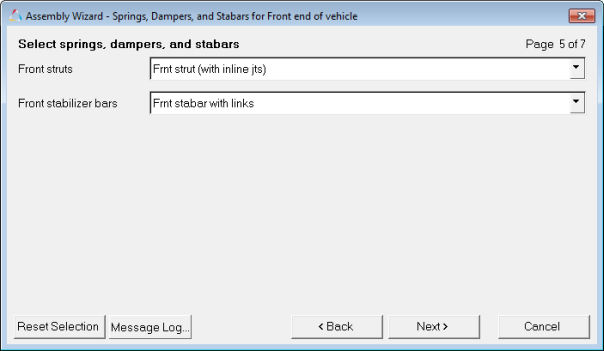
| 5. | Select the Front strut model (either inline joints or a single cylindrical joint that defines the strut motion). |
| - | Select either a stabar with links (a multiple-beam style stabilizer bar), or a two-piece stabilizer bar (rotational spring to simulate the bar stiffness). |
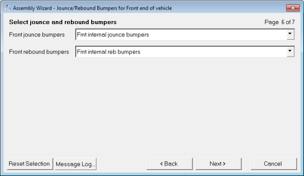
| 6. | Select an internal or external jounce and rebound bumper and click Next. |
Internal bumpers are integrated into the strut. External bumpers are separate from the strut.
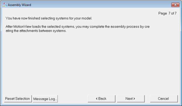
| 7. | At this point, you have selected all of the systems that will be in the model. You can go back and change the selections or move forward (Next) and build the model. |
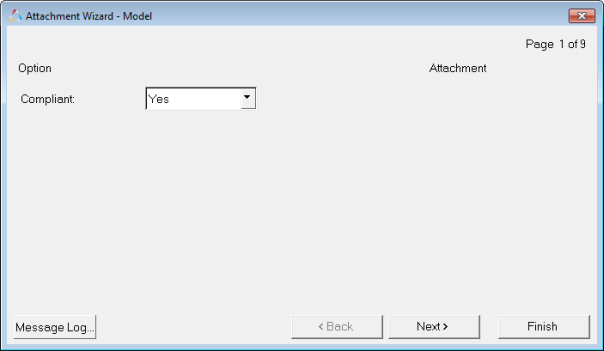
| 8. | You are now in the Attachment Wizard. For Compliant, select Yes to build a compliant model or No to build a kinematic model. |
Specific bushings can be toggled to rigid joints later in the process.
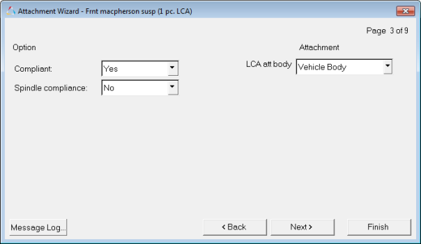
| 9. | Select Yes if the Lower Control Arm (LCA) bushings are compliant. |
| - | LCA att body allows the Lower Control Arm bushing to attach to the vehicle body or a subframe, if one is included. |
| - | Spindle Compliance includes a bushing in a series with the wheel revolute joint to simulate the compliance of the wheel bearing. |
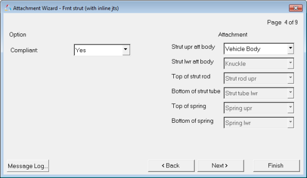
| 10. | Setting Compliant to No builds a universal joint as the connection of the top of the strut to the vehicle body. Selecting Yes will put a bushing at this location. |
| - | The Strut upr att body is typically the vehicle body or the subframe. |
| - | Options that are disabled/gray are for reference purposes only. |
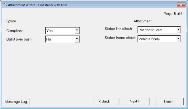
| 11. | Setting Compliant to Yes builds a bushing at the top and bottom of the stabilizer bar link and at the bar to the frame connection. Selecting No builds a kinematic connection of the bar to the frame and suspension components. |
| - | Setting Ball jt over bush to Yes builds a stabilizer bar link with a ball joint at each end and a bushing built over it. This results in a kinematic displacement with rotational forces. |
| - | The Attachment selections allow modification of the stabilizer bar attachments to the frame and suspension. |
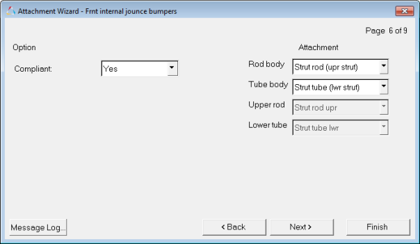
| 12. | The Compliant option for the Frnt internal jounce bumpers does nothing. Leave it set on the default setting (Yes). |
| - | The Attachment selections modify the parts that the internal jounce bumper connects to. |
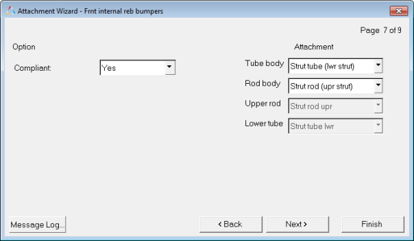
| 13. | The Compliant option for the Frnt internal reb bumpers does nothing. Leave it set on the default setting (Yes). |
The Attachment selections modify the parts that the internal rebound bumper connects to.
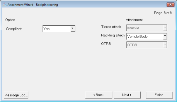
| 14. | The Compliant option for Rackpin steering builds a bushing between the steering rack and the body where the rack connects. |
| - | The Rackhsg attach option defines the body where the rack connects (typically the body or the subframe). |
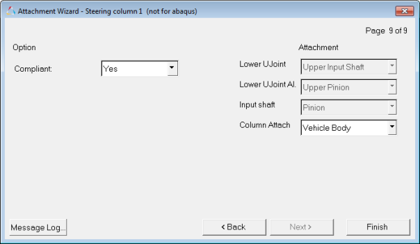
| 15. | The Compliant option for Steering column 1 builds either a bushing or a kinematic joint between the upper column and the vehicle body. |
| - | The Column Attach option modifies the body where the column attaches. |
At this point, you have built a complete front suspension. The model is now ready to be populated with correct hardpoint locations: springs, bushings, mass, inertia, and the other data required to build a model which will meet the needs of the suspension designer or analyst. Many of the options selected in the Assembly and Attachment Wizards can be modified using the MotionView interface. Systems can be easily turned off and on using the graphical user interface. It is recommended that a simple event be added, such as ride, and then the model be simulated as soon as it is built. Run the model as often as it is populated and try to keep it healthy instead of making big changes and checking it at the end.


