Altair Control State Equations (CSE) Powertrain |

|

|

|

|
|
Altair Control State Equations (CSE) Powertrain |

|

|

|

|
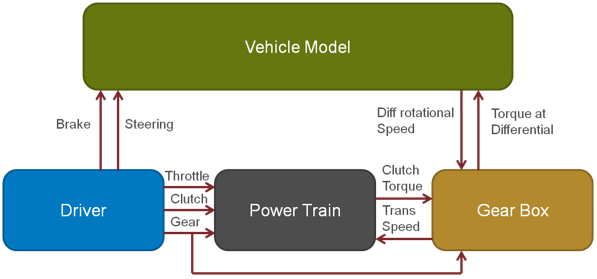
Altair’s MotionView/MotionSolve includes a simple Equations based Powertrain model. This can be used with all MotionView/MotionSolve vehicle models. The Altair CSE Powertrain is a mathematical formulation that represents an automobile IC engine powertrain in the form of Control State Equations (CSE). The CSE can be used independently and along with full vehicle models. The Equations represent the following components of the powertrain:
| • | Internal Combustion Engine (IC Engine) |
| • | Clutch |
The powertrain model has the ability to read and interpolate into a 3-D Engine Torque Map to determine the torque output of an engine based on vehicle states and throttle input. It further models a clutch which transmits the torque to the gear box and can be engaged and disengaged by a clutch input signal. This topic describes in detail the formulation used to model a Powertrain and also the parameters that determine the functioning of it.
The Powertrain is described by a Control State Equation (CSE). The powertrain can be loaded by importing the powertrain assembly in MotionView. This MotionView assembly contains the relevant Solver Arrays, CSE expressions, and Output Requests. Relevant attachments and attachment candidates are in place to assist the user to interface the powertrain model to the rest of the vehicle.
Alternatively, the powertrain can be interfaced directly into the Motion Solve deck. An example of the components in the solver deck is shown in the section – Motion Solve Example.
