Overview
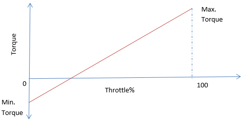
A linear torque map models a simple powertrain with a simple source and single gear. Only three parameters are required to define the powertrain. The powertrain requires torque at 0% throttle and 100% throttle. Source/Engine produces torque directly proportional to throttle, or in other words linearly interpolates torque at 0% and 100% to evaluate torque at intermediate throttle value.
Variations from conventional powertrain systems in MDLLIB
This information can be used to retrofit the powertrains to interface with advanced driver.
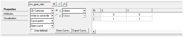
| 1. | Gear Ratio Curve: Curve that contains the information about the gear ratio of the gearbox. This curve is to maintain consistency with the IC Engine Friction Clutch Powertrain, that models manual transmission. Linear torque map has only one gear ratio. Gear 0 means neutral gear, and hence gear ratio is not important, since driver would never shift to gear 0. |
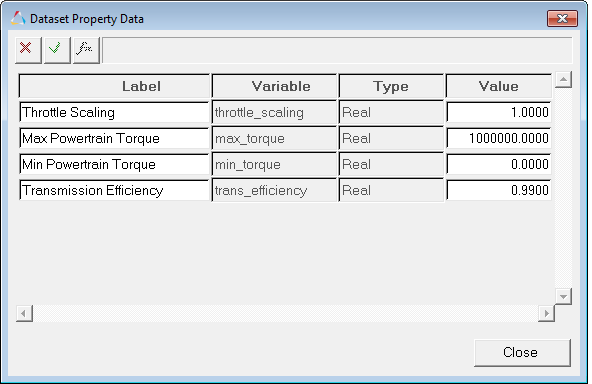
| 2. | Powertrain Dataset: Parameters to define the powertrain. |
Label
|
Default Value
|
Comments
|
Throttle Scaling
|
100
|
Variation of throttle: 0-100, or 0-1, or 0-any value.
Driver overrides this value with the value specified in the Altair Driver File under the THROTTLE_STANDARD block, SCALING_FACTOR parameter to maintain consistency between driver output and the powertrain expected throttle input.
|
Max. Powertrain Torque
|
10e6
|
In model units.
Toque output from the powertrain at 100% throttle.
|
Min. Powertrain Torque
|
0.00
|
In model units.
Toque output from the powertrain at 0% throttle.
|
Transmission Efficiency
|
0.99
|
Input omega/(output omega*Gear ratio).
|
| 3. | Differential Torque or Drive Torque: Torque output of the powertrain. |
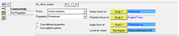
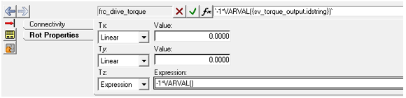
Tz – Expression = ‘-1*VARVAL({Torque Output Solver Variable IDstring})’
| 4. | Powertrain Array: IC Array that holds the data entered in the powertrain dataset. It is a good practice to parameterize this with the powertrain dataset. |
Index
|
Value
|
0
|
Reserved or No meaningful data.
*Generally used for debugging purposes only or as a place holder for something still in development.
|
1
|
Powertrain torque at 100% throttle.
|
2
|
Powertrain torque at 0% throttle.
|
3
|
Throttle Scaling
|
4
|
Reserved
|
5
|
Reserved
|
Solver Variable
|
Comments
|
Throttle Signal
|
| • | Placeholder for the throttle signal from driver/test rig. |
| • | If not overridden, it gives 0 throttle signal to the powertrain. |
| • | This signal will be required to be attached to the analysis. |
|
Gear Signal
|
| • | Present to resolve attachments of the analysis. |
| • | Also, present to maintain consistency with the IC Engine Friction Clutch Powertrain. |
|
Clutch Signal
|
Engine Speed
|
Drive Torque
|
| • | Solver signal that computes the powertrain torque given throttle input. |
| • | User defined properties. |
| • | User Expression – ‘USER(1, {Solver Array Powertrain ID}, {Solver Variable Throttle Signal ID})’. |
| • | Use local file and function name. |
| • | Local file – msautoutils. |
| • | Function name – VIRTUAL_POWERTRAIN. |
|


