About the FEA Model:
| • | Determine the nodes to externalize in the model. In other words, the flexible body to which you are attaching the nodes in the MBD model. |
| • | Create an Excel spreadsheet highlighting the external nodes to be used and include the node ID’s for each. Verify the component is in the same position as you require in the MBD model. |
| • | Note the units being used in the model and verify that these units are correct by measuring distance and mass. |
| • | Verify the degrees of freedom (DOF) of the external nodes, and which nodes can be externalized. Usually an RBE2 element works best. |
| Note | Certain elements cannot be attached to external nodes, such as RBE3 and CBAR. |
| • | Before exporting the model for use in MotionView’s Flexbody Prep Wizard, perform an element check on 1-D, 2-D, and 3-D elements to assure that there are no duplicate elements or issues with element properties. |
| • | Verify that any nodes that are used to attach the rigid body - which will be replaced with a flexible body - to other bodies in the MBD model are accounted for as attachment points. |
Creating Models
| • | Limit the amount of external nodes, as each node used generates an additional six modes in the solution. For example, if you request 20 modes, and you have 10 external nodes, then the model will contain 80 modes. |
| • | If the model requires that custom parameters be used, then you may have to use E-Compute to run the files. It is recommended that you turn off the element checking option (in the Flexbody Prep Wizard) in order to use E-Compute. |
Troubleshooting
If the model did not run:
| • | Does the pathname to the model contain any spaces, such as Vehicle FEA instead of Vehicle_FEA? If any spaces are in the pathname, the executable will not run. |
| • | Did you have custom parameters that were placed in the model using HyperMesh and are using the Flexbody Prep Wizard to run the model through OptiStruct? If so, these are removed from the file when it is run. You will have to run the files using E-Compute and then assemble them to create an .h3d file using Flexbody Prep Wizard. See To run the model with E-Compute. |
| Note | Parts can be mirrored using the H3D to H3D option in the Flexbody Prep Wizard. |
Verifying Flexbodies in MotionView
| • | Before any runs are made using the flexible body, verify the following: |
| • | Verify that the mass and inertias of the body are the same as the FEA and/or CAD model. To determine the mass and inertias in a HyperMesh model, select the File menu, Export option. |
| • | From the Template box, click Load and open the file install_directory\hw11.0\templates\summary\optistruct\mom_of_inertia. Write out a file for this specific model. |
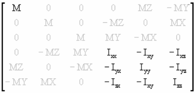
| • | Open the created file and select the last matrix on the output titled Inertia Matrix for Model (Using Center of Gravity As Center). The data is presented in the following manner, where the required values are bold: |
| • | Verify that the modal frequencies, as well as the mode shapes in the H3D file, are the same as the results in HyperMesh. |
| 1. | Output the .fem file of an FEA model from HyperMesh to OptiStruct. |
| 3. | From the FlexTools menu, select Flexbody Prep. |
| 4. | Select the FEA to H3D option. |
| 5. | Select the bulk data file (.fem) that was output from OptiStruct. |
| 6. | Select the interface nodes and modal information. |
| 7. | Select the correct units. |
| 8. | Perform a stress recovery. |
| 9. | List the external node ideas with plus sign, "+", in between, such as 1 + 2 + 3 + 4. |
| 10. | You may need to select MEGAGRAM for mass units, as this is often the mass unit used in FEA. |
| Note | Flexbody Prep removes many custom parameters created in HyperMesh by default. If this does not allow files without the custom parameters, there are two options: the files can be manually edited and run through Flexbody Prep again, or run through E-Compute. For more information, see To run the model with E-Compute. |
|
| 2. | From the FlexTools menu, select Flex Prep. |
| 3. | Select the FEA to H3D option. |
| 4. | Select the bulk data file (.fem) that was output from OptiStruct. |
| 5. | Select the three edited .fem files. |
| 6. | Specify the name for the .h3d file. Give the file the same name as the original filename, but with the suffix .flex. |
| 7. | Choose the same interface nodes and modal information as specified earlier. |
| 8. | Choose the correct units. |
|
| 1. | From the FlexTools menu, select Flex Prep. |
The FlexBodyPrep dialog is displayed.
| 2. | Select the Create OptiStruct-prp (preparation) file option. |
| 3. | Click on the Select Bulk Data file (fem/nas/bdf/dat) file browser  , and select the original .fem file. , and select the original .fem file. |
| 4. | In the Save the fem file as text box, specify the name for the .h3d file. |
| Note | Do not include the pathname when entering in the name for the .h3d file, as this will cause E-compute to fail when it is run. |
| 5. | Select the same units and modal data. |
| 6. | If you want to perform a stress or strain recovery, activate the appropriate check box. |
| 8. | After the program runs, an .h3d file is created and can be used in MotionView. |
When running the model using E-Compute, the six rigid body modes are included. When using Flexbody Prep Wizard directly, the six modes are automatically excluded.
|


