|
»Click here to display Table of Contents«
|

Import CAD or FE |

|

|

|

|
|
Import CAD or FE |
|
|
|

|
|
»Click here to display Table of Contents«
|
Import CAD or FE |
|
|
|
|
|
Import CAD or FE |
|
|
|
|
From the Tools menu, select Import CAD or FE to display the Import CAD or FE dialog:
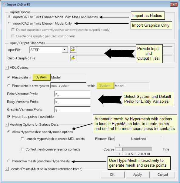
Import CAD or FE dialog
The Import CAD or FE dialog contains the following sections and fields:
Import Options |
|
|
|
|
Import CAD or Finite Element Model With Mass and Inertias |
Use this option to import CAD or FE model as bodies with mass and inertia. Refer to Note 1 (below) for available CAD/FE formats with this option. |
|
|
Import CAD or Finite Element Model Only |
Use this option to import graphics only. |
|
|
|
Do not import into currently active window (save to output file only) |
Select this option to convert CAD to graphics H3D without importing into the current active MotionView window. |
|
|
Create one graphic per CAD component |
Select this option to create a unique graphic entity for each component in the H3D file, otherwise, only one graphic entity will be created for all components. |
Input/Output Filenames |
|
|
|
|
Input File |
The file containing the source data for the translation. The file can be a CAD component or an FE component. Select the CAD or FE type from the drop-down menu. |
|
|
Output |
Specify the H3D file name which holds the graphic information. |
|
MDL Options |
|
|
|
|
Place data in System Place data in new system |
Use either of these options to have the resulting MDL data loaded into a particular system. |
|
|
Point, Body, or Graphic Varname Prefix |
Control the prefix for the variable names for the created points, bodies, and graphics respectively. |
|
|
Import free points if available |
Any free points available in CAD will be imported as MDL point. |
|
Meshing Options for Surface Data |
|
|
|
|
Allow HyperMesh to specify mesh options |
Use this option to allow HyperMesh to mesh the surfaces with the default mesh options. |
|
|
|
Launch HyperMesh |
Launches HyperMesh specifically with a macro, allowing you to select FE nodes that will become MDL points. |
|
|
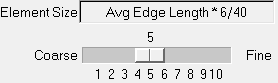
Control mesh coarseness for contacts |
Activate the check box to access options which allow you to control the mesh coarseness for the contacts. Use the slider bar to adjust the mesh from coarse to fine (1 - 10). The default setting is 5.
The Element Size field displays...... |
|
Interactive mesh (launches HyperMesh) |
Launches HyperMesh with the source file loaded, which allows you to mesh as per user choice and macros to create MDL points. |
|
Locator Points |
Three tags in the coordinate system of the geometry file that are stored in the H3D graphics file. During import to the MDL model, these three points can be matched to three MDL points and you can select auto-position, auto-orient, and auto-scale based on those three points. For HyperMesh files, node IDs can be used in place of coordinates. |
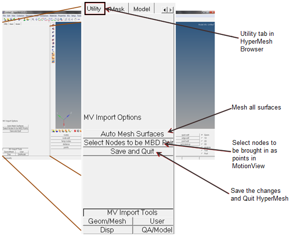
||
If Interactive Mesh (launches HyperMesh) is selected under Meshing Options for Surface Data, HyperMesh is launched and the file is imported into Hypermesh. The Utility tab is displayed in the Browser that contains tools that can be used for MotionView import. Using these tools, all surfaces can be meshed at once, and nodes can be selected to be created as points in MotionView. You can also use other general features of HyperMesh to mesh as per choice, edit the geometry, arrange components in component collectors, etc. Once all editing is completed, use Save and Quit tool under the Utility Browser to return to MotionView.
If Import CAD or Finite Element Model With Mass and Inertias is selected, another dialog will appear that list the bodies with volume and mass information (once the process in Hypermesh is completed). This dialog also has choice to specify input file units so that the correct mass and inertia can be calculated.
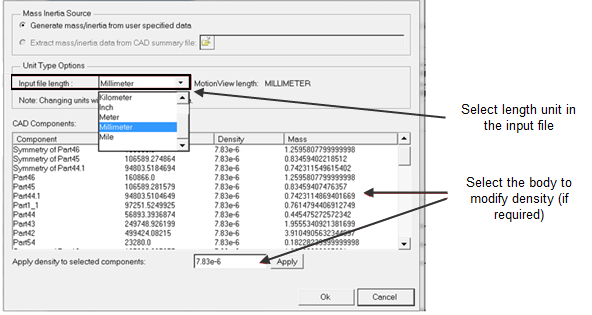
Clicking Ok completes the process by creating the bodies, CG points, and graphics.
Catia |
HyperMesh |
JT |
Nastran |
OptiStruct |
Parasolid |
ProE |
SolidWorks |
STEP |
UG |
|
|
| 2. | The following additional CAD/FE types are supported for Import CAD/FE only: |
Abaqus |
ACIS |
Ansys |
DXF |
DXF |
HyperMesh Ascii |
Ideas |
IGES/IGS |
LS-Dyna |
Madymo |
Marc |
Pamcrash2G |
PDGS |
Permas |
OptiStruct |
VDAFS |
|
|
| 3. | Some of the CAD formats like Catia and UG could need additional CAD reader license and library settings. Refer to CAD Reader Support for more details. |
| 4. | The densities assigned are only applicable at the time of the import process, and they cannot be changed once the import is completed. The volume information will not be available until after the import process is complete. |
| 5. | The accuracy and tolerance of mass/inertia and CG location for FE models can vary marginally based on the coarseness of the mesh. |
| 6. | The mesh is used for graphic visualization only since this import is restricted to rigid bodies only. There are no quality requirements on the mesh. |
| 7. | This interface works well for up to a medium size CAD assembly (~100 components). A very large CAD assembly import may encounter memory restrictions. |