MotionView User's Guide

MV-1030: Creating a System Definition Using the MotionView GUI

MV-1030: Creating a System Definition Using the MotionView GUI

Previous topic Next topic No expanding text in this topic  

MV-1030: Creating a System Definition Using the MotionView GUI

Previous topic Next topic JavaScript is required for expanding text JavaScript is required for the print function  

In the earlier exercise, you learned about MDL and authoring a definition using the MDL language through a text editor.  In general, many of the definitions (such as systems, datasets, and analyses) are created using the MotionView graphical user interface.  This tutorial demonstrates how to create a system using the GUI and save its definition to a file, which is an alternate way of creating a definition other than using the text editor.

Exercise: Creating a System Definition Using the GUI.

This exercise will help you learn to:

Create systems using the MotionView graphical user interface
Export a system definition to a file
Reuse the saved definition by instantiating it in the model

Step 1: Creating a system instance.

1.To create a system, right-click on Model in the Project Browser and select Add > System/Assembly.

OR

-Right-click on the System/Assembly panel button systems_analyses_icon_mv on the Container Entity toolbar.

The Add System/Assembly dialog is displayed.

2.Select the System radio button and click Next.

The Add System dialog is displayed.

3.Specify sys_pendu as the Variable, Pendulum as the Label, and def_sys_pendu as the Definition Name.
4.Click OK.

The Pendulum system system_browser_icon_mv is added to the model and its corresponding panel is displayed.

Step 2: Adding attachments to the system.

1.From the Attachments tab, click on the Add button (located in the middle of the panel).

The Add an Attachment dialog is displayed.

2.Specify the Label as Attachment Point and arg_p for the Variable, select Point (from the drop-down menu), and verify that the Type is set to Single only.
3.Click OK.
4.Add another attachment with the Label as Attachment Body and Variable as arg_b, select Body from the drop-down menu, and specify the Type as Single only.

mv-1030-02

We have created two attachments to the Pendulum system which will be used to attach this system to other entities of a model.

Notice that the both of the newly created attachments are Unresolved, which means that the attachments are not yet referring to another entity in the model.

5.Double click on the mv-1030_point_collector collector.

The Select a Point dialog is displayed.

mv-1030_select_a_point_dialog

6.Select Global Origin from the list on the right side of the dialog and click OK.
7.Similarly, click the mv-1030_body_collector collector, select Ground Body from the model tree, and click OK.

Step 3: Adding entities to the system.

1.Select Pendulum in the Project Browser.
2.Right-click and select Add > Reference Entity > point-24 Point.

OR

-Right-click on the Points panel button point-24 on the Reference Entity toolbar).

The Add Point or PointPair dialog is displayed.

3.Specify the Label as Mass CG, Variable as p_cg, and the Type as Single.

mv-1030-10

4.Click OK.

The Points panel is displayed with the properties of Mass CG.

5.From the Properties tab, click in the X Coordinate field and click on the fx_button button on the Expression bar.

The Expression Builder is displayed.

mv-1030_expression_builder_dialog

6.Delete 0.0 from the Expression area (located at the top of the dialog).
7.From the model tree, expand the Pendulum > Attachments > Attachment Point folders and select x (x is one of the property attributes of the point entity Attachment point).

mv-1030-04

8.Click the Add button (located in the middle of the dialog).

arg_p.x is automatically filled in the Expression area.

9.Append +50 to this expression.

The complete expression should now read: arg_p.x+50.

mv-1030_expression_builder_dialog_ex2

10.Click OK to close the dialog.

Through the above steps the point Mass CG is parameterized with regard to the X coordinate of the point Attachment Point and is placed at a distance of 50 length units in the X direction.

11.Repeat the above steps for the Y and Z Coordinates, by selecting attribute y and z respectively in the expression bar.  Specify the expression for the Y Coordinate as arg_p.y and arg_p.z+100 for the Z Coordinate.

Alternatively, the expressions in Y and Z can be filled by copying the arg_p.x+50 expression from X Coordinate and editing it.

mv-1030-11

NoteThe background color of the field changes for parametric expressions.
12.Right-click on the Pendulum system in the Project Browser and select Add > Reference Entity > entityMultibodies-24 Body.

The Add Body or BodyPair dialog is displayed.

13.Enter Mass for the Label and b_mass for the Variable, and click OK.
14.From the Properties tab specify the Mass as 1 and the Inertia properties as 1000 for Ixx, Iyy and Izz respectively.

mv-1030-12

15.Click on the CM Coordinates tab and check the Use center of mass coordinate system option.  Pick the point Mass CG as the Origin.

mv-1030-13

16.Right-click on the Pendulum system in the Project Browser and select Add > Reference Entity > Graphic.

The Add "Graphic" dialog is displayed.

17.Specify the Label as Rod, the Variable as gcyl_rod, the Type as Cylinder, and click OK.

The Graphics panel is displayed.

18.From the Connectivity tab; double click on the Body collector for Parent and pick Mass in the Pendulum system, click on the Point collector and pick Mass CG as Origin, and for Direction double click the Point collector and select the attachment to the system Attachment Point.

mv-1030_graphics_panel_cylinder

19.Go to the Properties tab and change the value of Radius 1 to 2.
20.Next, add a Sphere graphic by right-clicking on the Pendulum system in the Project Browser and selecting Add > Reference Entity > Graphic.
21.Specify the Label as Mass, the Variable as gsph_mass, the Type as Sphere, and click OK.
22.Pick Mass for the Parent body and Mass CG as the Origin.

mv-1030_graphics_panel_sphere

23.From the Properties tab, specify 25 for the Radius.

mv-1030_graphics_panel_properties_tab

24.Right-click on the Pendulum system in the Project Browser and select Add > Constraint > Joint.

The Add Joint or JointPair dialog is displayed.

25.Select Revolute Joint from the drop-down menu, specify the Label as Pivot, the Variable as j_pivot, the Type as Single, and click OK.

The Joints panel is displayed.

26.From the Connectivity tab, double click on body1_collector_mv and select Mass from the Select a Body dialog (model tree).  For the second body, click on the body2_collector_mv collector and browse through the model tree (Model > Pendulum > Attachments) and select Attachment Body.

mv-1030_select_a_body_dialog

NoteAlternatively, you can click on the Global Triad (at the bottom left of the triad) to pick Ground Body via the Attachment Body.
27.Similarly, for Origin select Attachment Point (located under Model > Pendulum > Attachments).  Use the Alignment axis drop-down menu to change from Point to Vector and select Global Y for the Alignment axis.

mv-1030_joint_panel

28.Save the model fileSaveModel-24 to your <working directory> as pend_gui.mdl.

Step 4: Exporting the system definition.

1.Select the Pendulum system in the Project Browser and click on the Import/Export tab in the Systems/Assembly panel.
2.Select the Export option.

mv-1030_sys_assembly_panel_export

3.Click on the Select file file browser mv-tut_folder_icon and browse to your <working directory>.
4.Specify the name of the file as sys_pend_gui.mdl by clicking on the folder icon and clicking on Save.
5.Open the above file in a text editor.

The system definition content will look as displayed below:

*DefineSystem( def_sys_pendu, arg_p, arg_b )

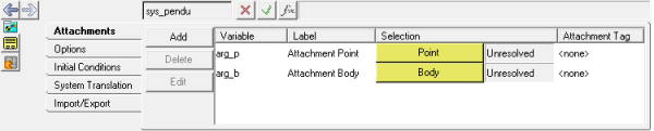
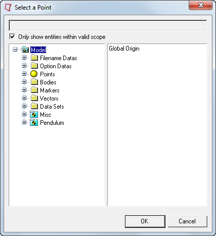
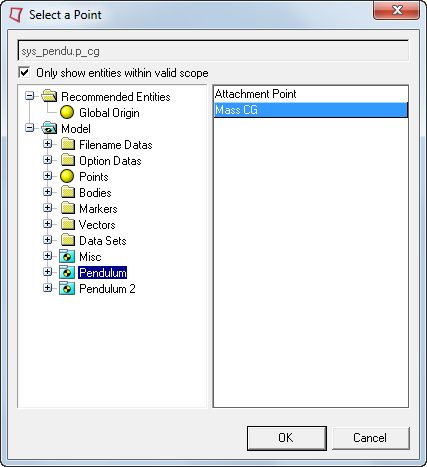
 *Attachment( arg_p, "Attachment Point", Point, "Select attachment.", P_Global_Origin,  )

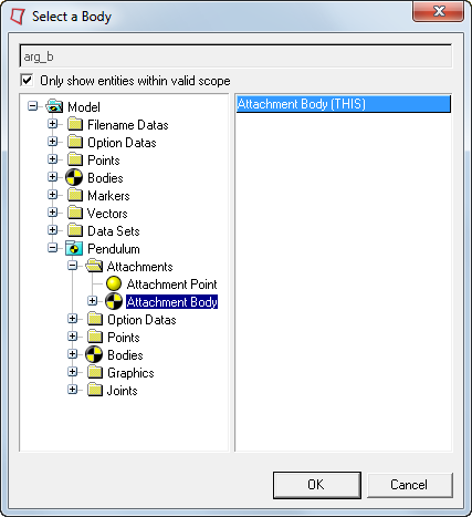
 *Attachment( arg_b, "Attachment Body", Body, "Select attachment.", B_Ground,  )

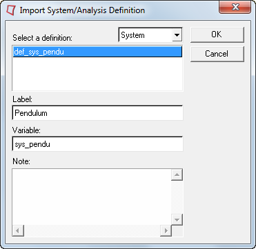
 *SetDefaultSystemInstance( sys_pendu, "Pendulum" )

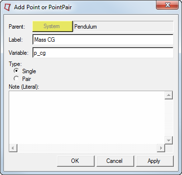
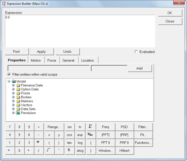
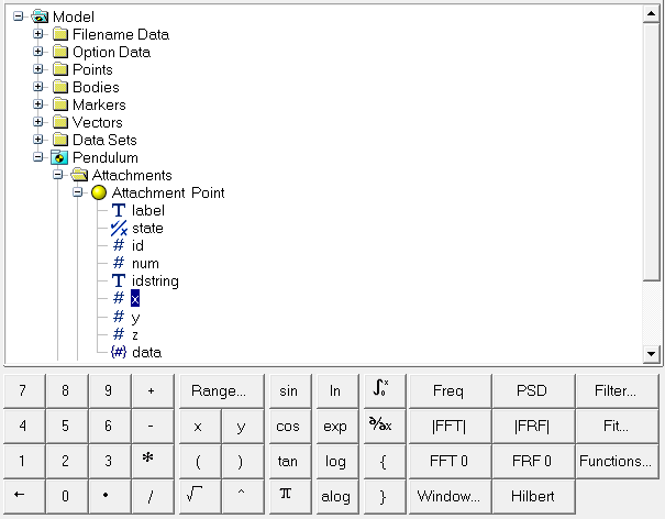
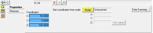
 *Point( p_cg, "Mass CG" )

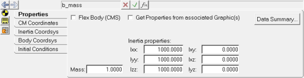
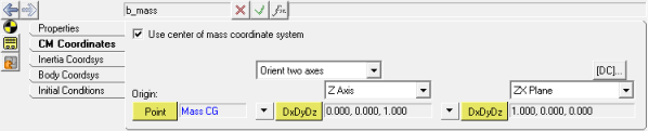
 *Body( b_mass, "Mass", p_cg, , , ,  )

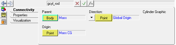
 *Graphic( gcyl_rod, "Rod", CYLINDER, b_mass, p_cg, POINT, arg_p, 2.0, gcyl_rod.r1, , 0.0, CAPBOTH )

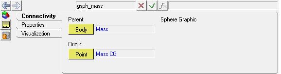
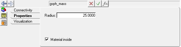
 *Graphic( gsph_mass, "Mass", SPHERE, b_mass, p_cg, 25.0 )

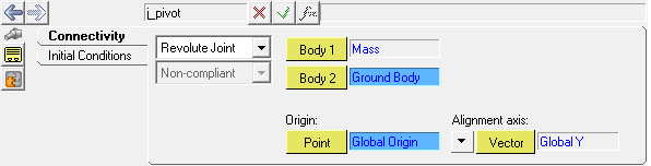
 *RevJoint( j_pivot, "Pivot", b_mass, arg_b, arg_p, VECTOR, V_Global_Y )

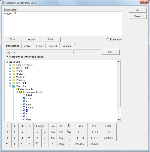
 *SetPoint( p_cg,                       arg_p.x+50, arg_p.y, arg_p.z+100 )

 *SetBodyInertia( b_mass,                     1.0, 1000.0, 1000.0, 1000.0, 0.0, 0.0, 0.0 )

 *Set( b_mass.usecm, true )

*EndDefine()

NoteThe Export option is only available for Systems and Analyses.  For other definitions like Datasets or Templates, the definition can be copied from the model .mdl file.

Step 5: Instantiating the system definition.

1.Select the Model system in the Project Browser.
2.Click the Import/Export tab in the Systems/Assembly panel.
3.Click on the Select file file browser mv-tut_folder_icon and browse to your <working directory>.
4.Select the sys_pend_gui.mdl file and click Open.

mv-1030_sys_assembly_panel_import

5.Click the Import button.

The Import System/Analysis Definition dialog is displayed. 

mv-1030_sys_analysis_def_dialog

6.Select def_sys_pendu.
7.Change the Label to Pendulum 2 and the Variable to sys_pendu_2.
8.Click OK.

The system definition is instantiated.

9.Select the Pendulum 2 system in the Project Browser.
10.Go to the Attachments tab and resolve the attachments in the following manner:
-Double click on the mv-1030_point_collector collector.  In the model tree that appears, click on the Pendulum system, select Mass CG from the list on the right, and click OK.

mv-1030_select_a_point_dialog_ex2

-Click on the mv-1030_body_collector collector.  In the model tree that appears, click on the Pendulum system, select Mass from the list on the right, and click OK.
11.Save the model fileSaveModel-24 to your <working directory> as pend_2_gui.mdl.

The same system definition can be reused to instantiate several times either within the same model or in a different model.